Flight Dynamics & Advanced Control
A Cirrus SR22 hand-flown in X-Plane and reduced to five dynamic modes against the military handling standard, then an LQR stability augmentation system that flies an F-16 with its centre of gravity pushed past the neutral point.
The brief
Third-year unit taught as two halves and submitted as one report in December 2025. Flight dynamics: trim and linearisation as a nonlinear root-find, canard versus conventional stability worked through on the Beechcraft Starship, the coupled aerodynamics of an oblique wing, and a full flight-test report. Advanced control: identify a plant from a measured step, design pitch controllers in the frequency domain, then stabilise a statically unstable F-16 and find out what breaks when the actuators cannot keep up.
Flight test
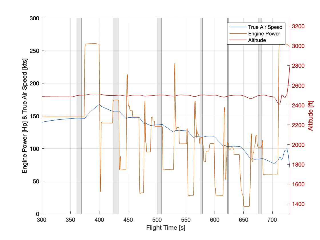
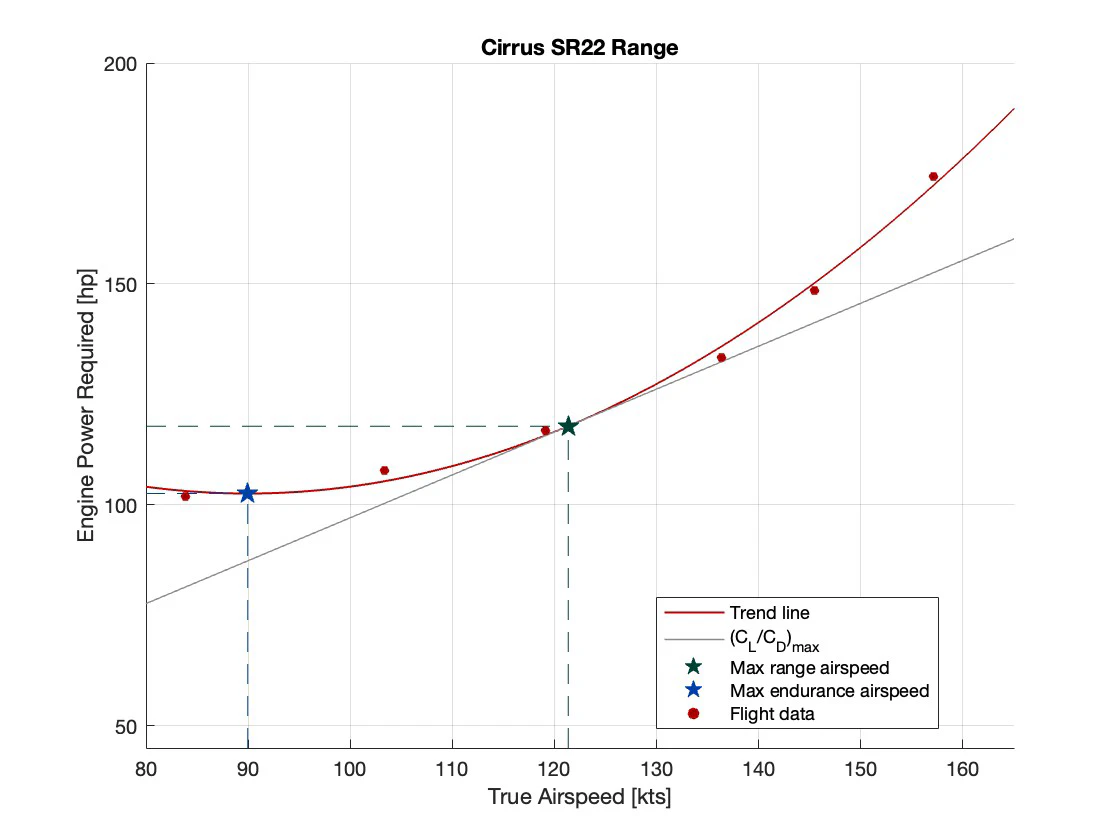
A Cirrus SR22 with a Continental IO-550-N was flown in X-Plane 12 and treated as a real test article: standard atmosphere, no wind, clean configuration, and every procedure written to NATO AGARDograph 300 doctrine. The performance sweep held 2,500 ft on autopilot while the throttle was stepped down through the speed range, giving a power-required curve whose minimum point is best endurance and whose tangent through the origin is best range.
Against the certified pilot's operating handbook at 55 percent power, the simulator produced 976 nautical miles of range to the book's 941. Fuel flow matched to within 0.2 percent, so the engine model is right; the airframe is simply four knots too clean, missing the antennas, gap seals and paint of a real aircraft.
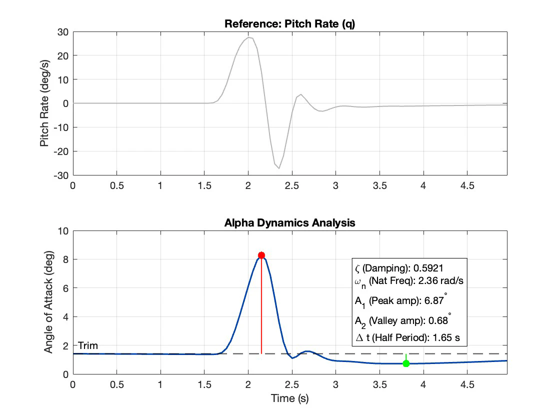
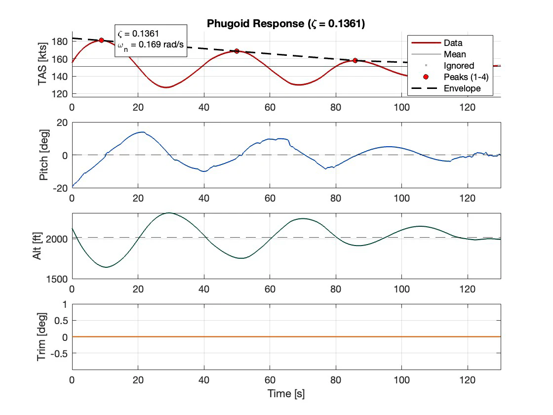
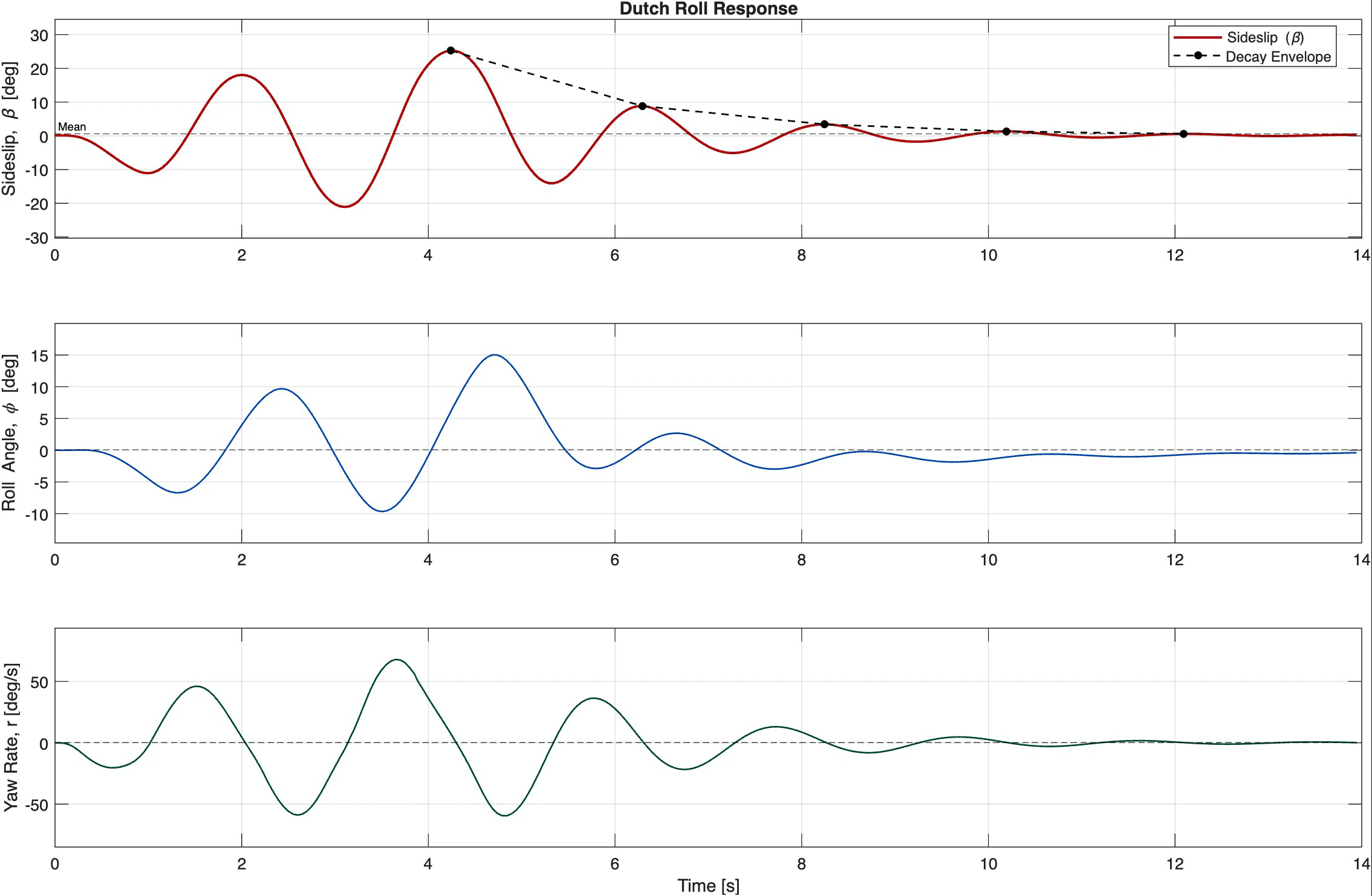
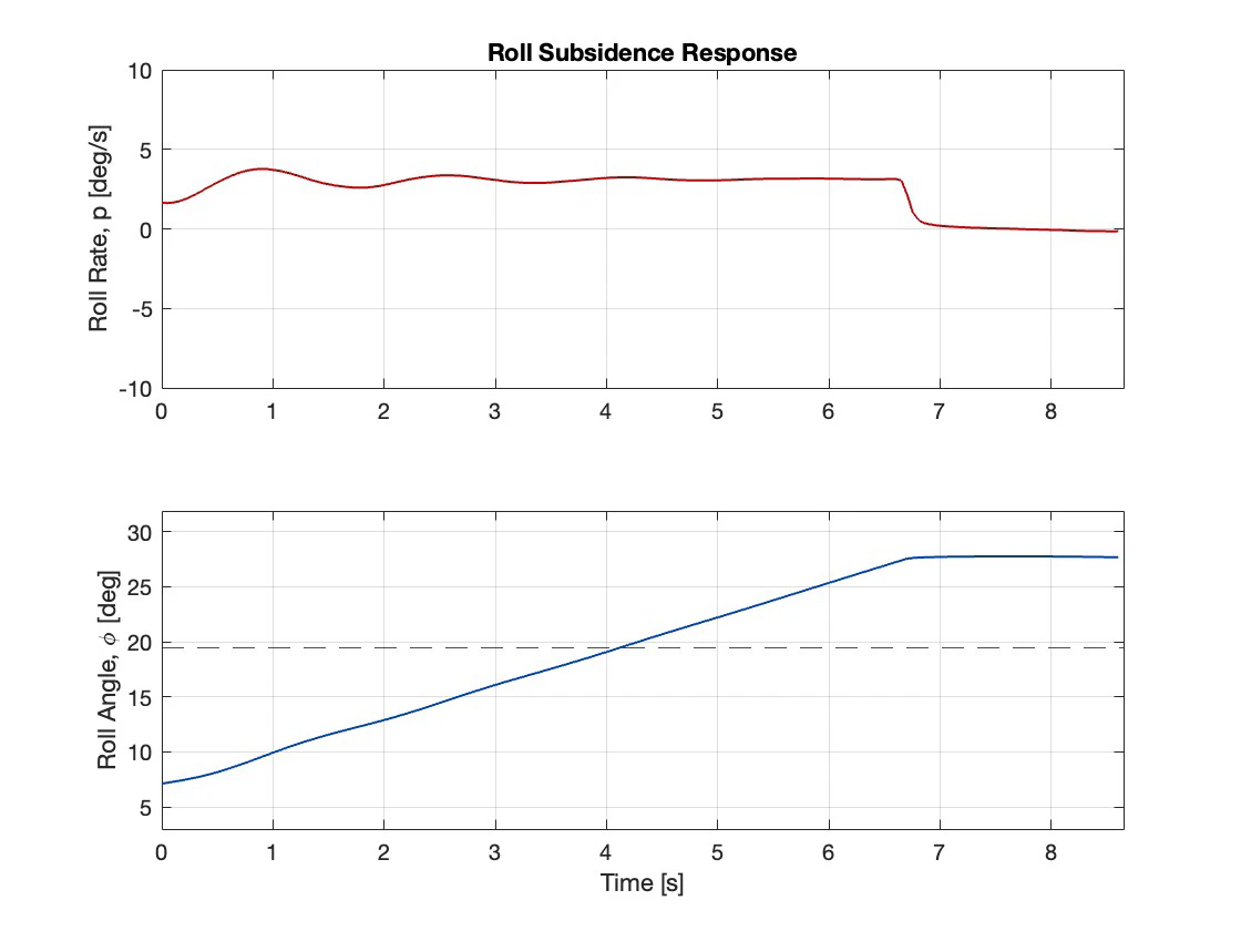
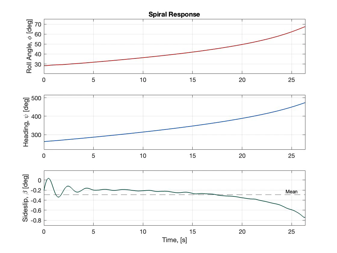
Then all five dynamic modes were excited by hand and reduced. Short period from a one-second elevator pulse, phugoid from a stick-down input, dutch roll from a rudder doublet, roll subsidence from neutralising the ailerons in a bank, and spiral from releasing the controls in a 28 degree turn. Every one meets Level 1 of MIL-F-8785C, including the spiral, which is genuinely unstable but diverges slowly enough to pass. The phugoid frequency came out at 0.169 rad/s against Lanchester's 0.173, and the ratio of phugoid to short period frequency is 0.07, so the two modes do not talk to each other.
Oblique wing
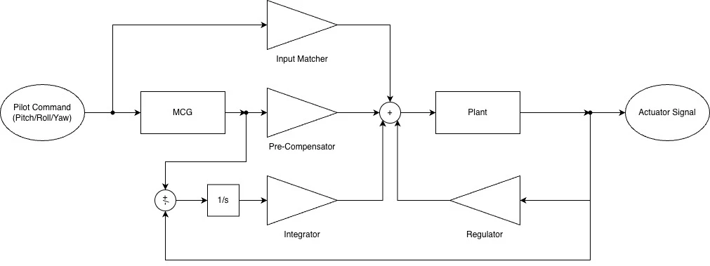
The other half of the flight dynamics section asks what happens when an aircraft has no plane of symmetry. On the NASA AD-1, angle of attack alone generates a rolling moment and, through leading-edge suction that no longer cancels left to right, a net sideforce. Strip theory gives the coupled aileron derivatives. The modes stop being longitudinal and lateral-directional and start mixing: in one open-loop case at 65 degrees of skew, a 3.9 degree change in incidence produced a full 360 degree roll, and the residual lateral acceleration reached 0.332 against a Level 1 limit of 0.05. The answer in the literature is implicit model following, where a feedforward path inverts the airframe's own coupling and a regulator holds it to an ideal model, so the pilot never feels the asymmetry.
Identify, then control
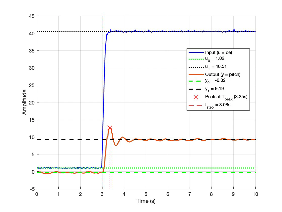
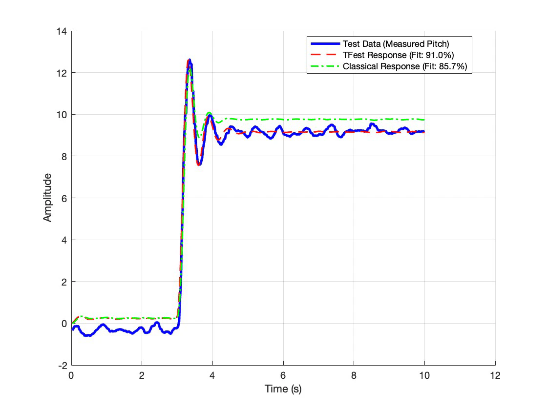
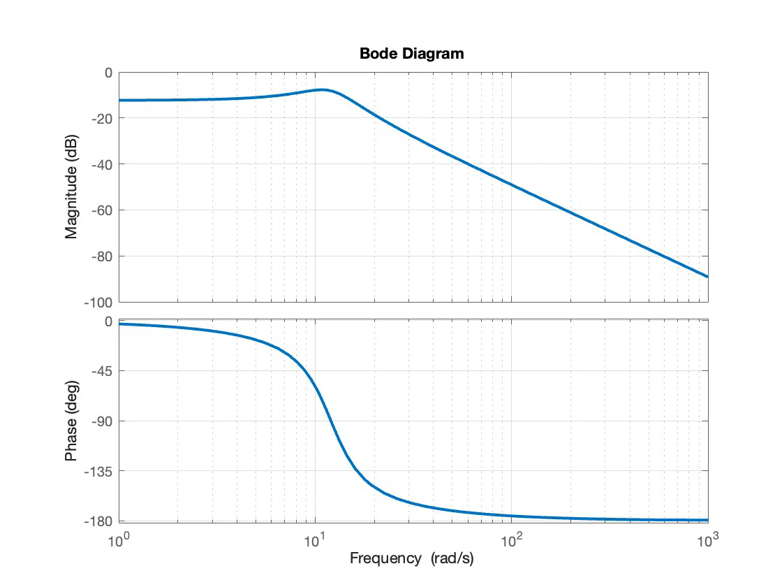
The control half starts from data rather than a model. A measured pitch step gives a steady-state gain of 0.2408, a peak time of 0.275 seconds and 36.1 percent overshoot, which invert to a damping ratio of 0.3084 and a natural frequency of 12.024 rad/s, and so to a second-order transfer function. MATLAB's tfest fits the same record better, 91.0 percent against 85.7, but the hand-derived model was deliberately matched to the peak rather than the steady state, and it is the one carried forward.
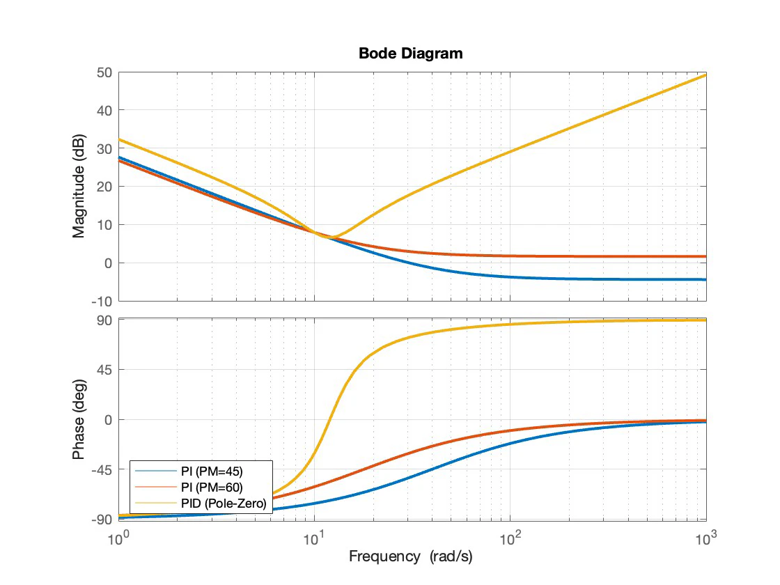
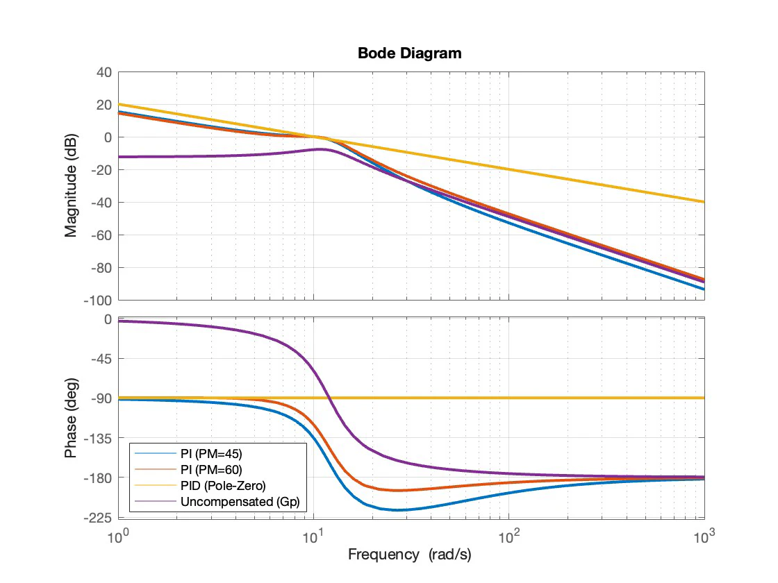
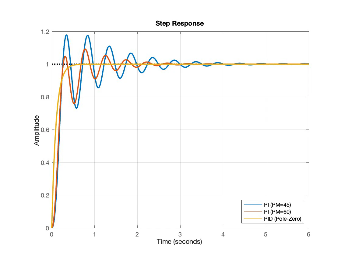
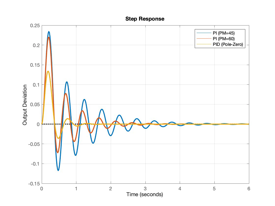
Three pitch controllers were then designed to a 10 rad/s crossover: an aggressive PI at 45 degrees of phase margin, a robust PI at 60, and a PID whose two zeros cancel the plant's poles outright. On paper the PID wins everything, with no overshoot and a third of the settling time. The report's conclusion is that it is still the wrong answer: the cancellation only holds while the real plant matches the model exactly, and the derivative term amplifies noise. The robust PI is the one to build.
An F-16 that will not fly itself
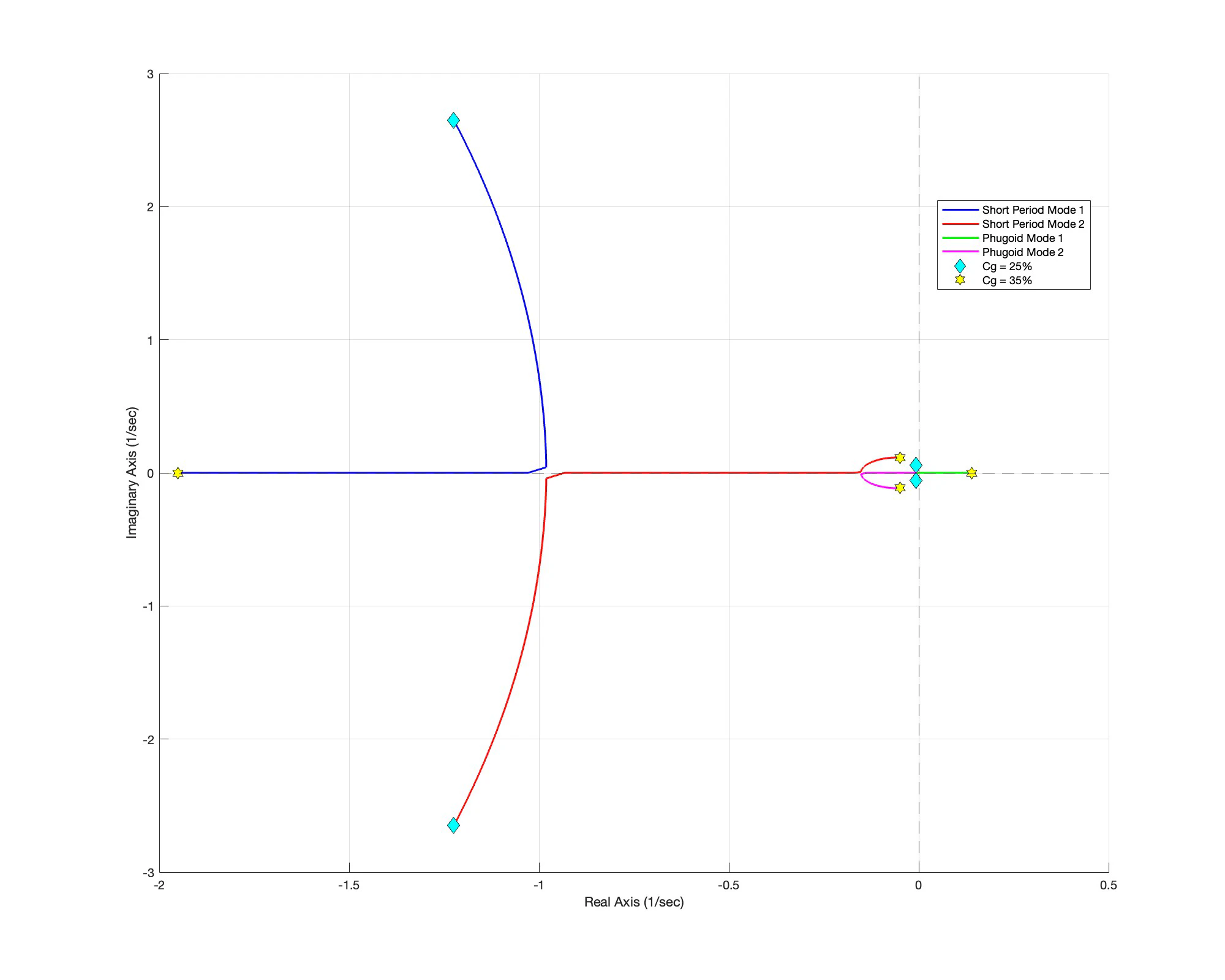
Sweeping the centre of gravity of the Stevens and Lewis nonlinear F-16 from 25 to 35 percent of mean aerodynamic chord walks the longitudinal poles across the plane. The short period pair meets the real axis and splits; more seriously, one phugoid root crosses the imaginary axis and ends at about +0.14 per second. That is not an oscillation with poor damping, it is a monotonic divergence, and it is what the controller has to hold.
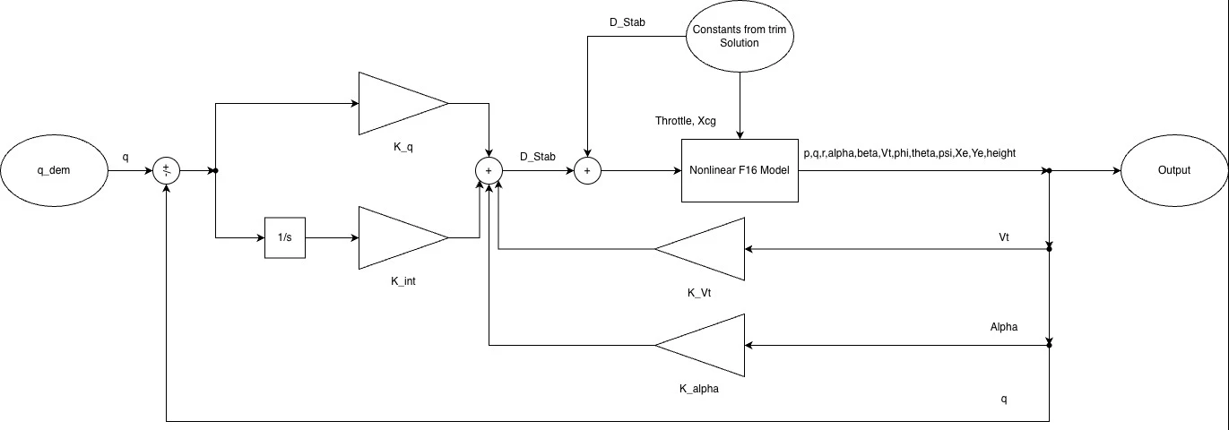
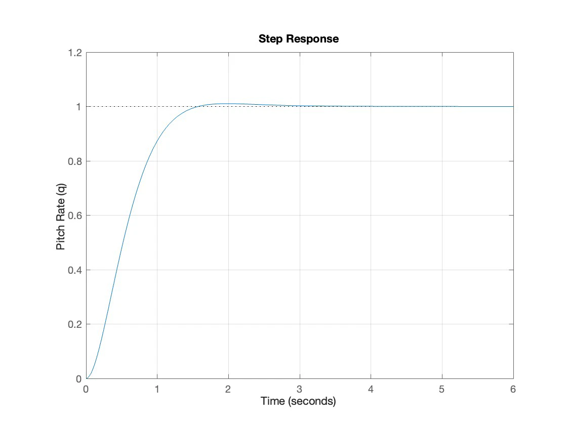
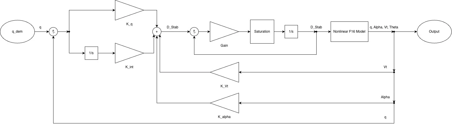
The stability augmentation system is a PI on pitch rate with full state feedback, with the gains chosen by LQR. The interesting part is the tuning, which was driven by handling-qualities criteria rather than by a cost number. Cheapening the control effort from R equals 1.5 to 0.1 moved the closed-loop natural frequency from a sluggish 1.1 rad/s to 2.95, the centre of Cook's satisfactory region and short of the abrupt boundary at 4. Relaxing the pitch rate penalty from 25 to 10 brought the damping down from a deadbeat 0.9 to 0.86, trading a stiff response for the five percent overshoot a pilot reads as the aircraft rotating freely.
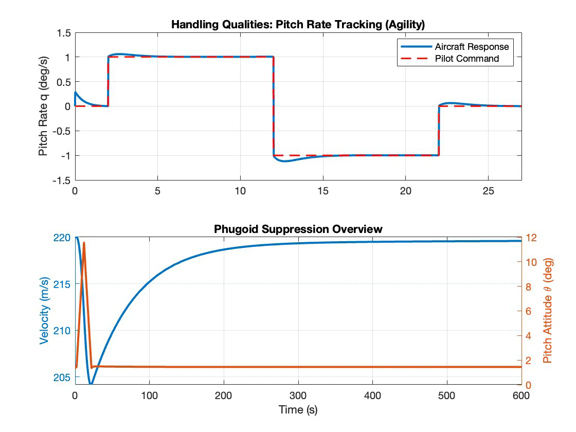
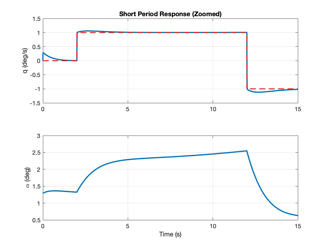
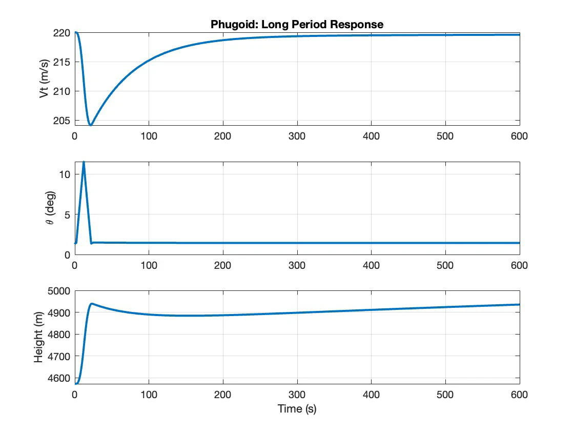
Flown on the nonlinear model at the 220 m/s design trim, a plus and minus one degree per second doublet tracks with almost no lag, settles inside two seconds and never excites the phugoid.
Where it stops working
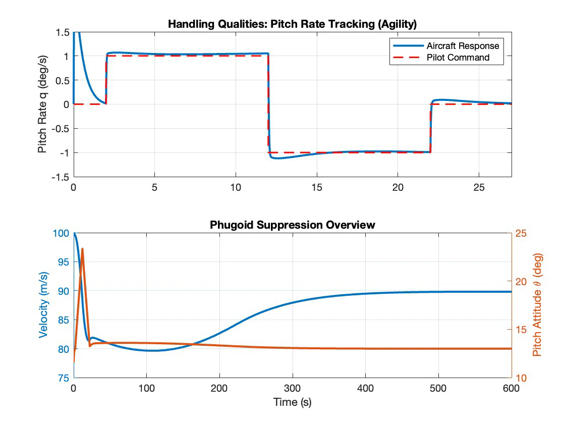
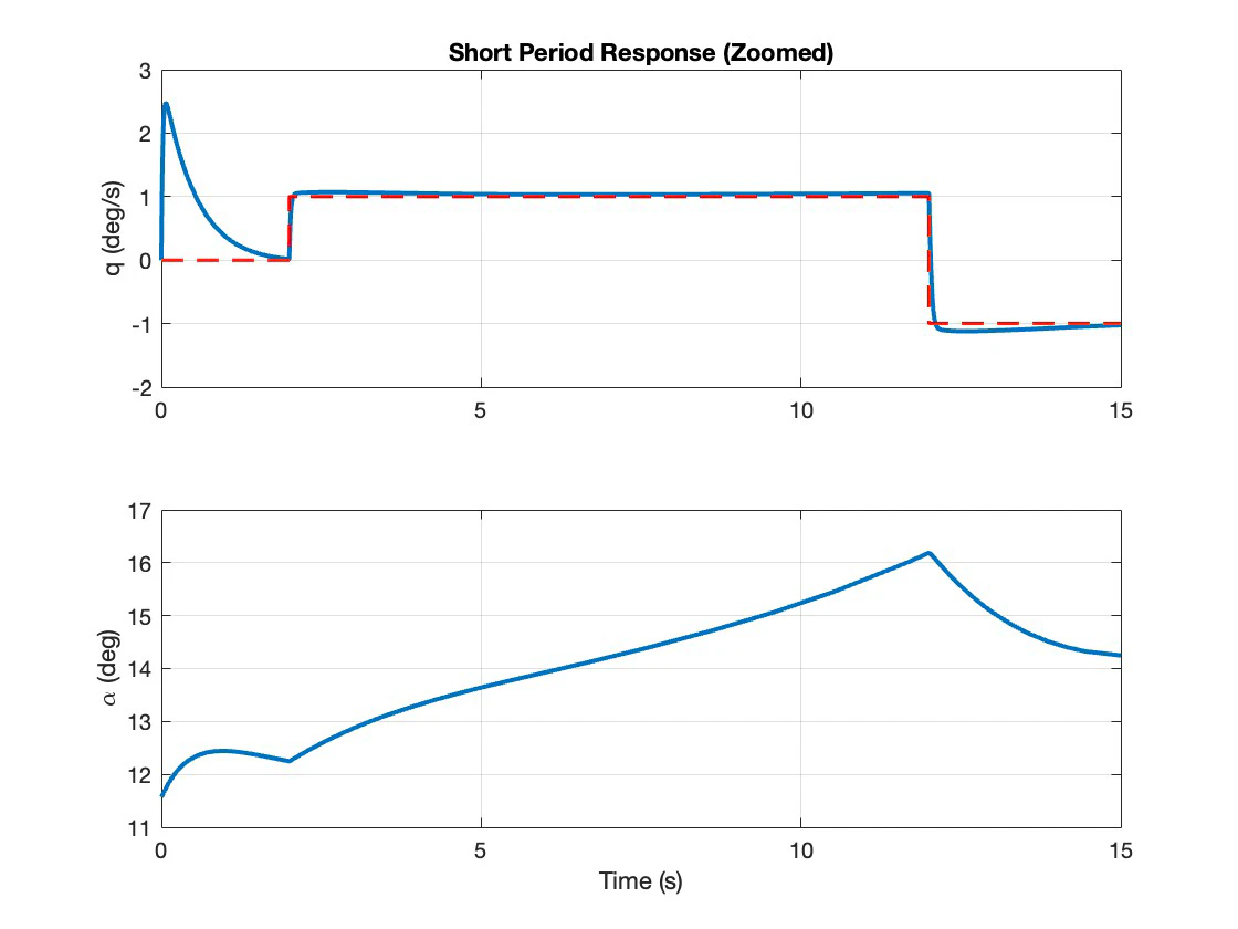
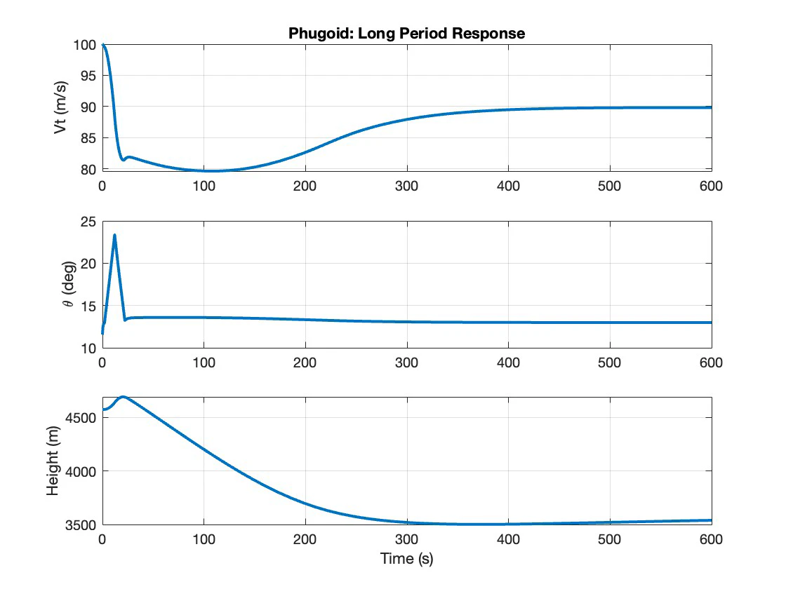
The same fixed-gain controller was then flown at 100 m/s, where dynamic pressure is a fifth of the design value and the trim angle of attack is 12 degrees rather than 1.4. Pitch rate tracking still looks respectable. Everything else does not: incidence climbs past 16 degrees without settling, velocity collapses to 80 m/s before recovering to 90, and the aircraft descends 1,100 metres over ten minutes on the back side of the power curve. Gain scheduling on dynamic pressure, an alpha limiter and an auto-throttle are what it needs.
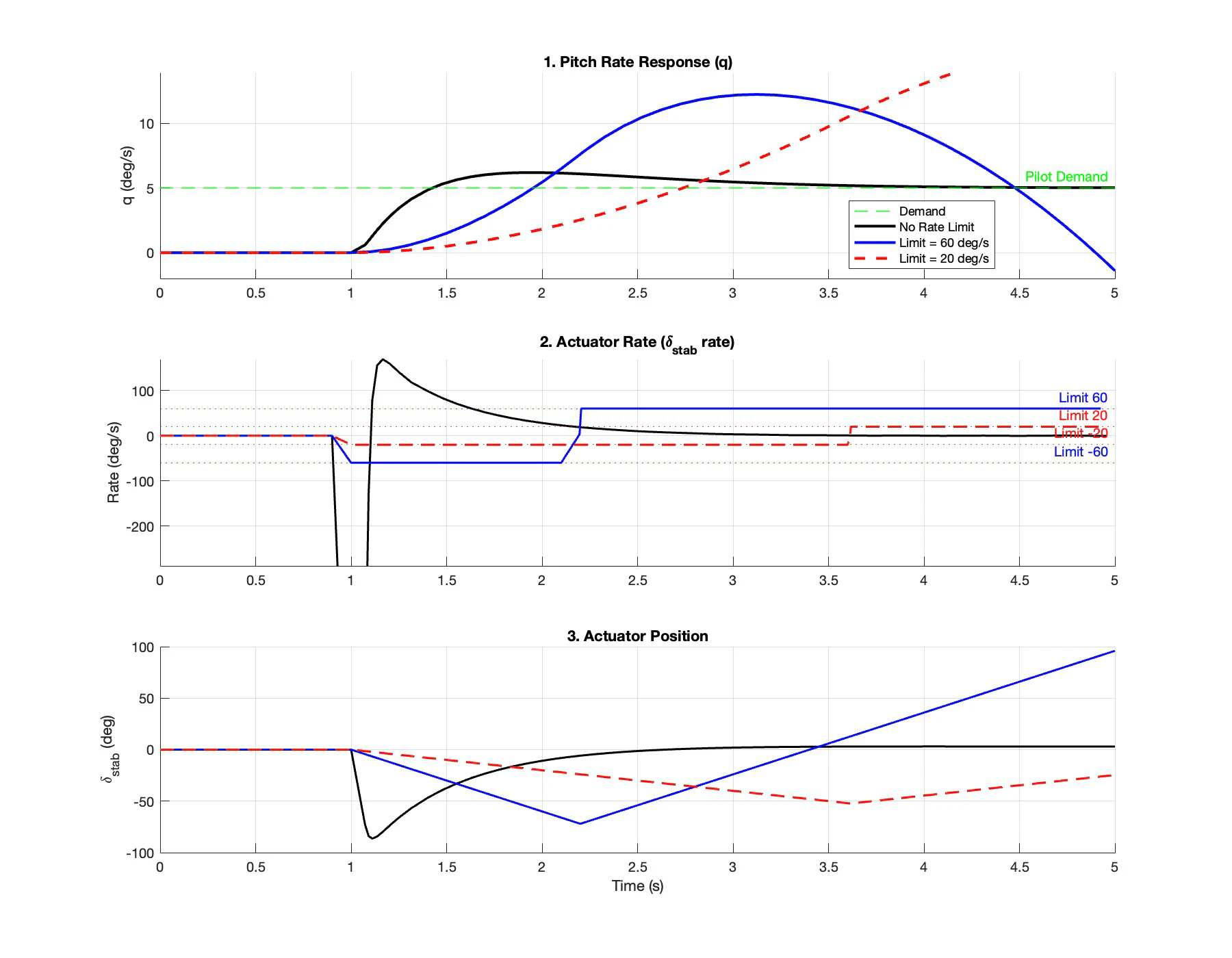
The last section removes the other convenient fiction. An ideal response to a step demand asks the stabilator for an infinite initial rate. Limited to 60 degrees per second the actuator saturates, the integrator winds up while the error persists, and the response overshoots past 8 degrees per second before it can unwind. Limited to 20 it becomes a slow ramp and the handling drops to Level 3. Anti-windup logic and prefiltering the pilot's command are the two standard answers.
Laboratory
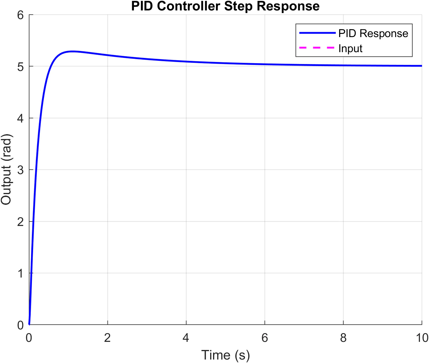
Alongside the coursework, the same method ran on hardware in the Quanser lab: identify the rig, get a second-order plant out of it, then tune the PID with a particle swarm. The swarm was the one written from scratch for the second-year controls coursework, re-parameterised to 200 particles and scored on a cost that weights steady-state error ten times over overshoot, settling and rise time.
Report
The submitted coursework, covering both halves of the unit: trim and stability, the oblique wing study, the flight test report, system identification, the pitch controllers, the F-16 stability augmentation system and the actuator rate limiting analysis.