
BSEP Engine 2
Codename Snow WhiteThe world's first CP1 aluminium rocket engine: a lightweight Al-Fe-Zr chamber with a coaxial-swirl injector, run to full duration on its maiden fire.
An alloy's first flame
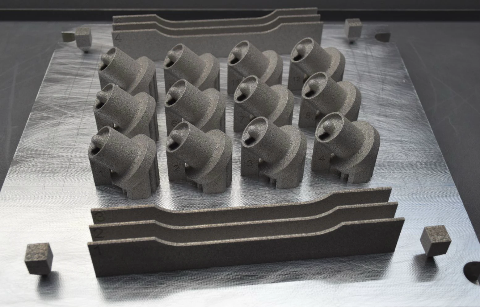
Engine 2 kept Engine 1's cycle and design point, 5 kN at 20 bar on IPA and nitrous oxide at an O/F of 3, and changed what it was made of. The chamber moved from Inconel 718 to CP-1, an Al-Fe-Zr aluminium, cutting chamber mass roughly threefold. It was the first time CP-1 had been used in a liquid rocket engine. On top sat a new coaxial-swirl injector plate for better mixing, efficiency and a route to throttling. The chamber was printed on the AMCM machine through the MTC beam-shaping project. I was Propulsion Lead.
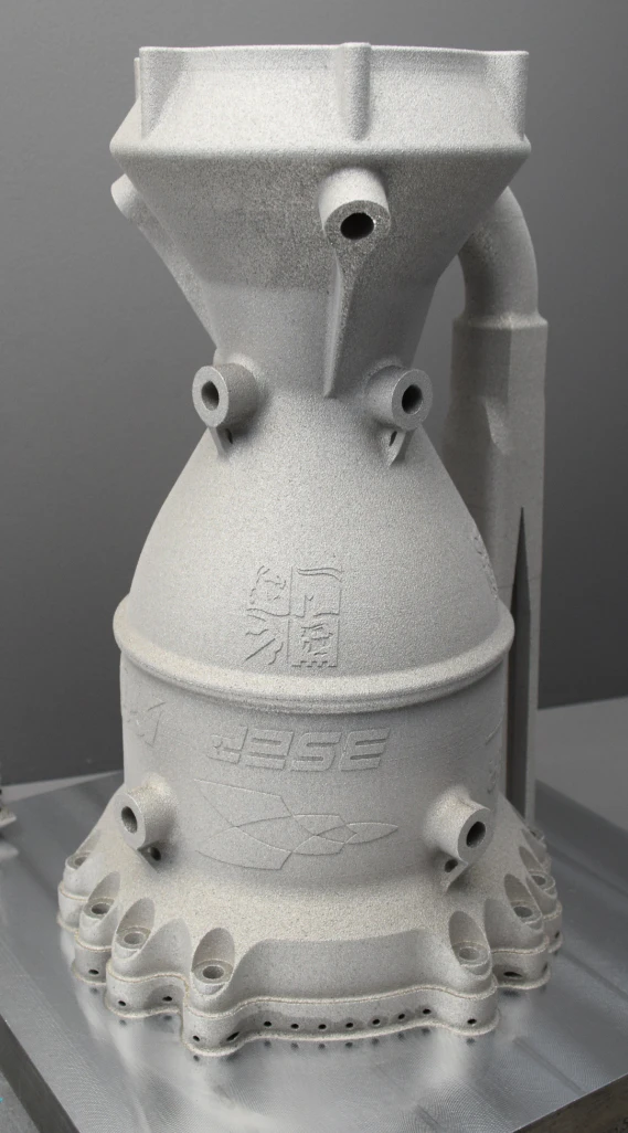
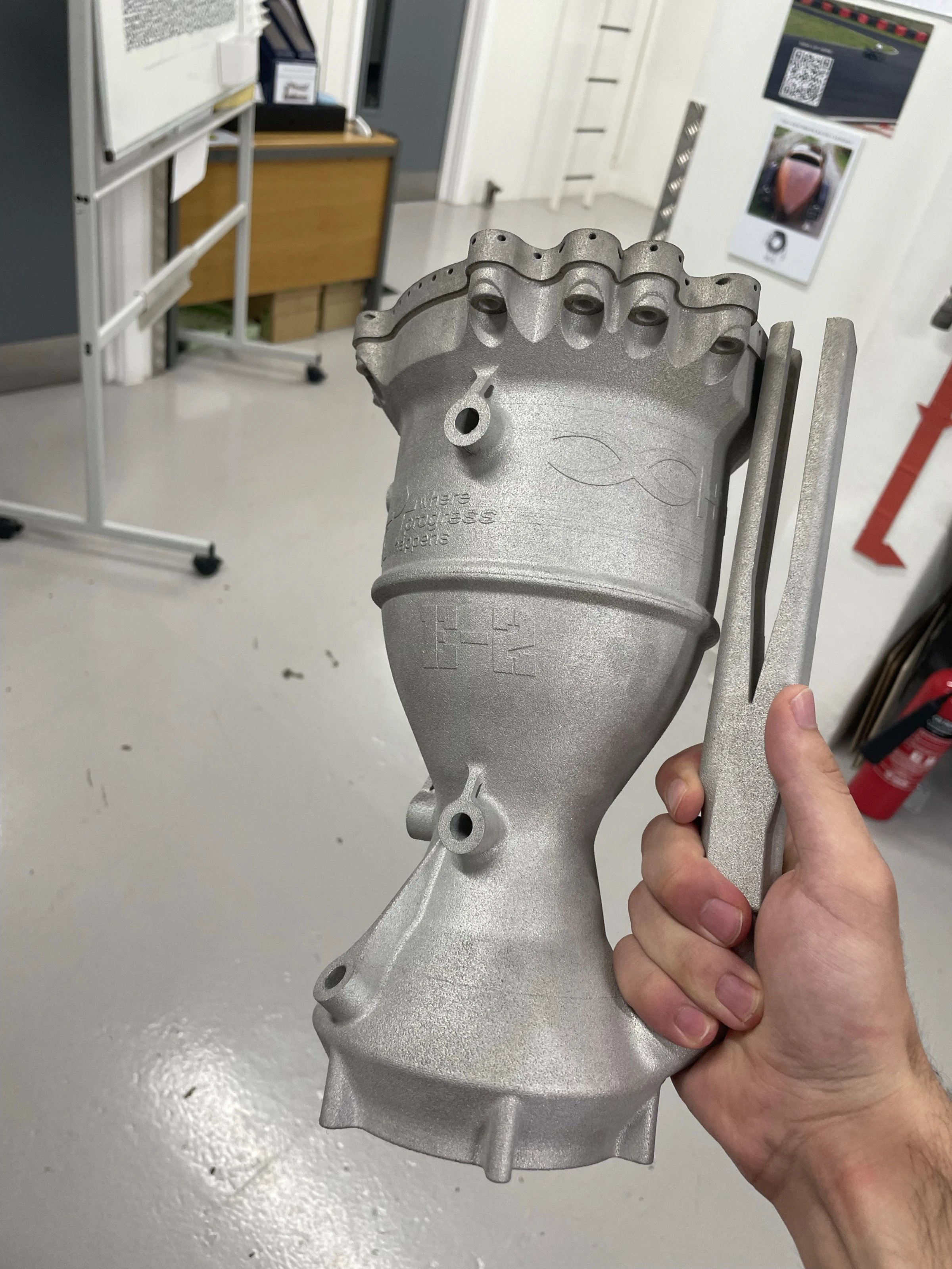
Loading model 0%
Making it
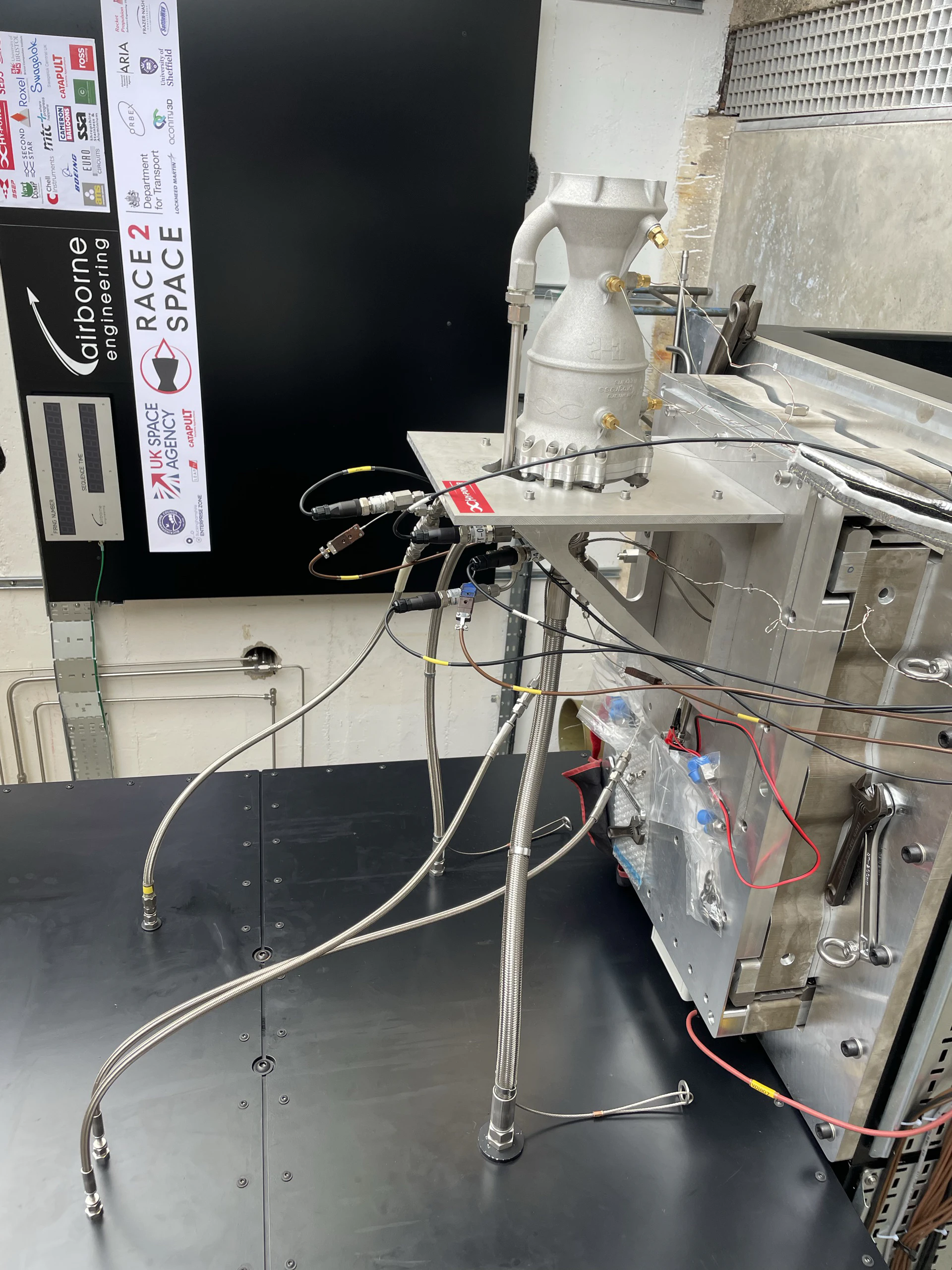
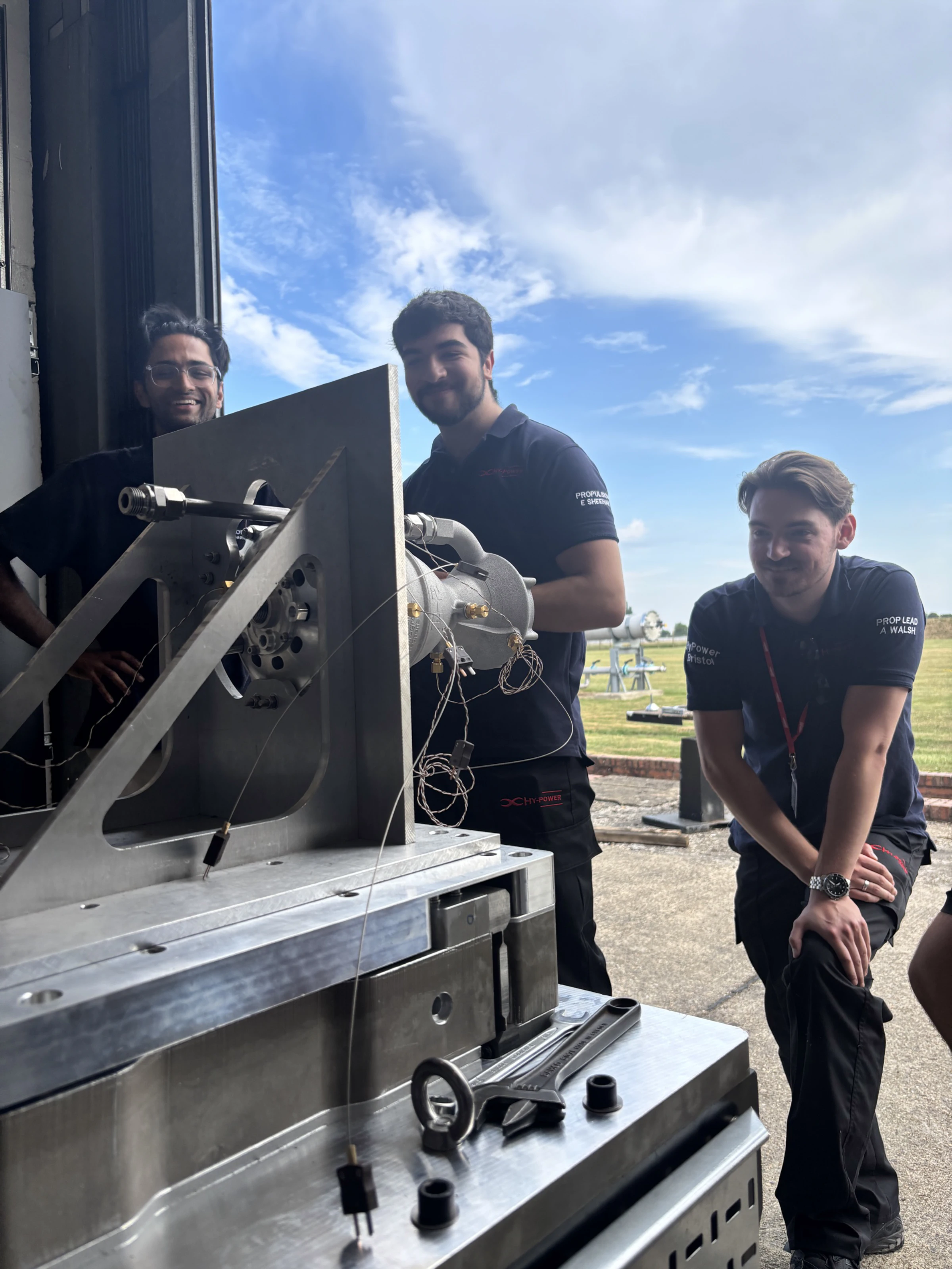
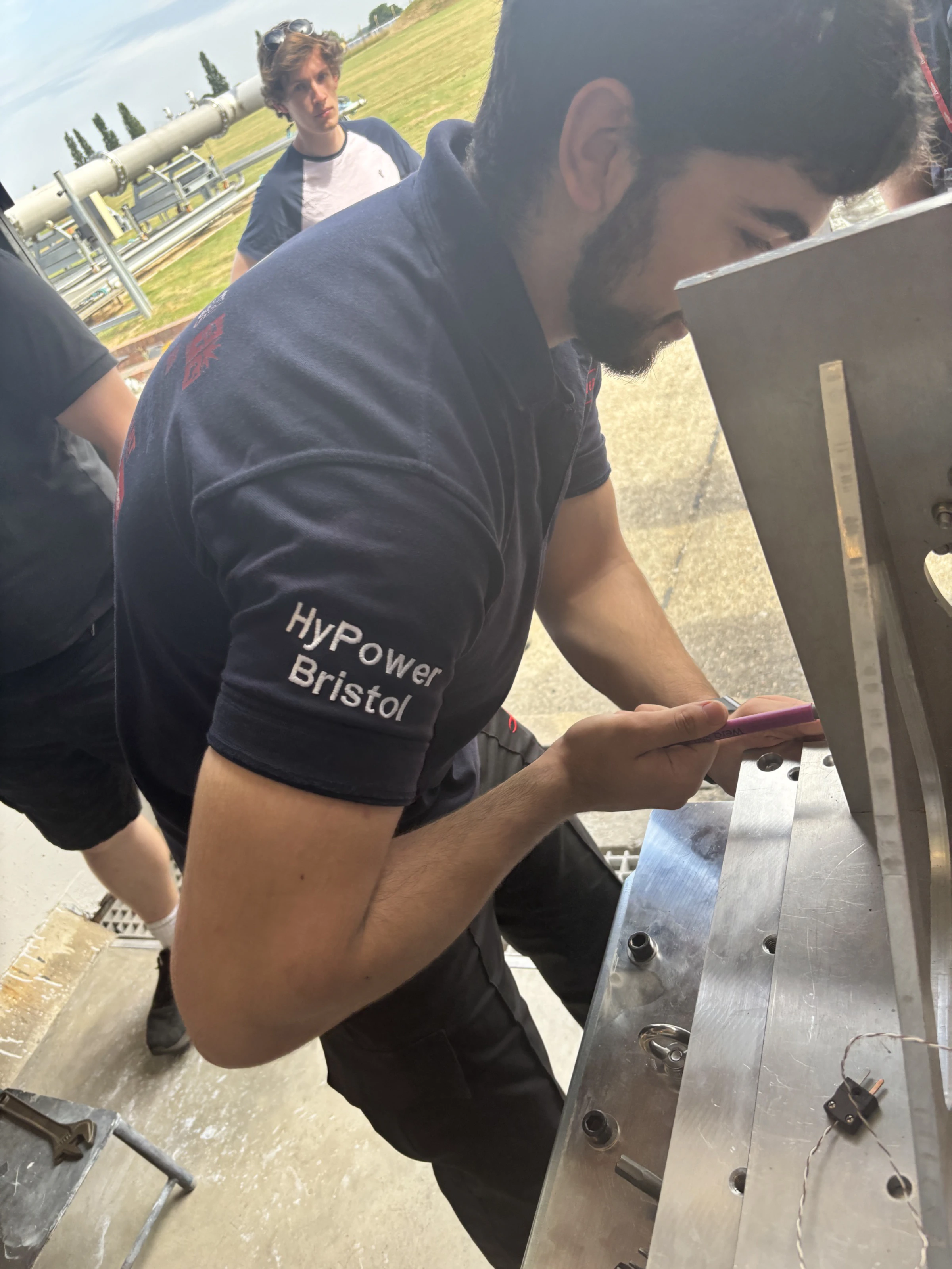
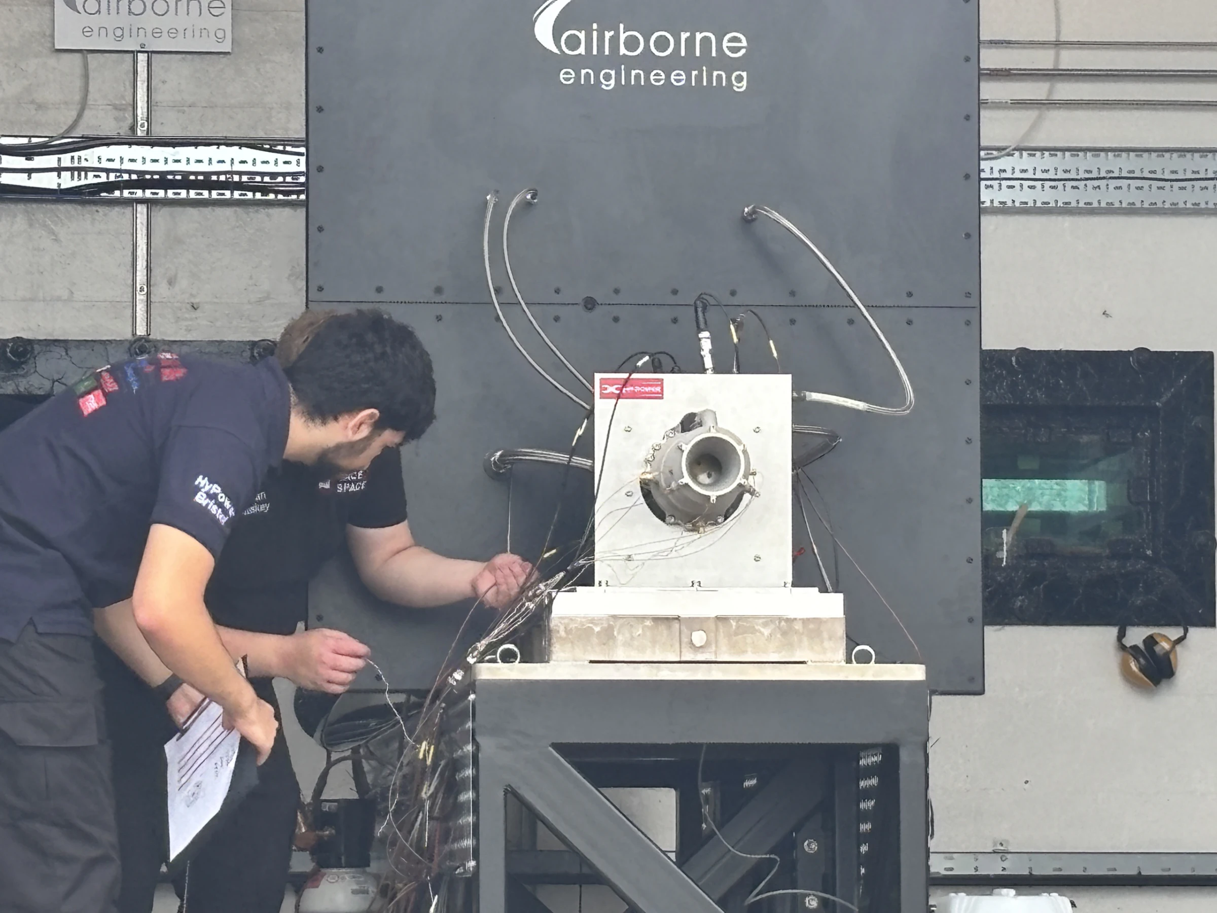
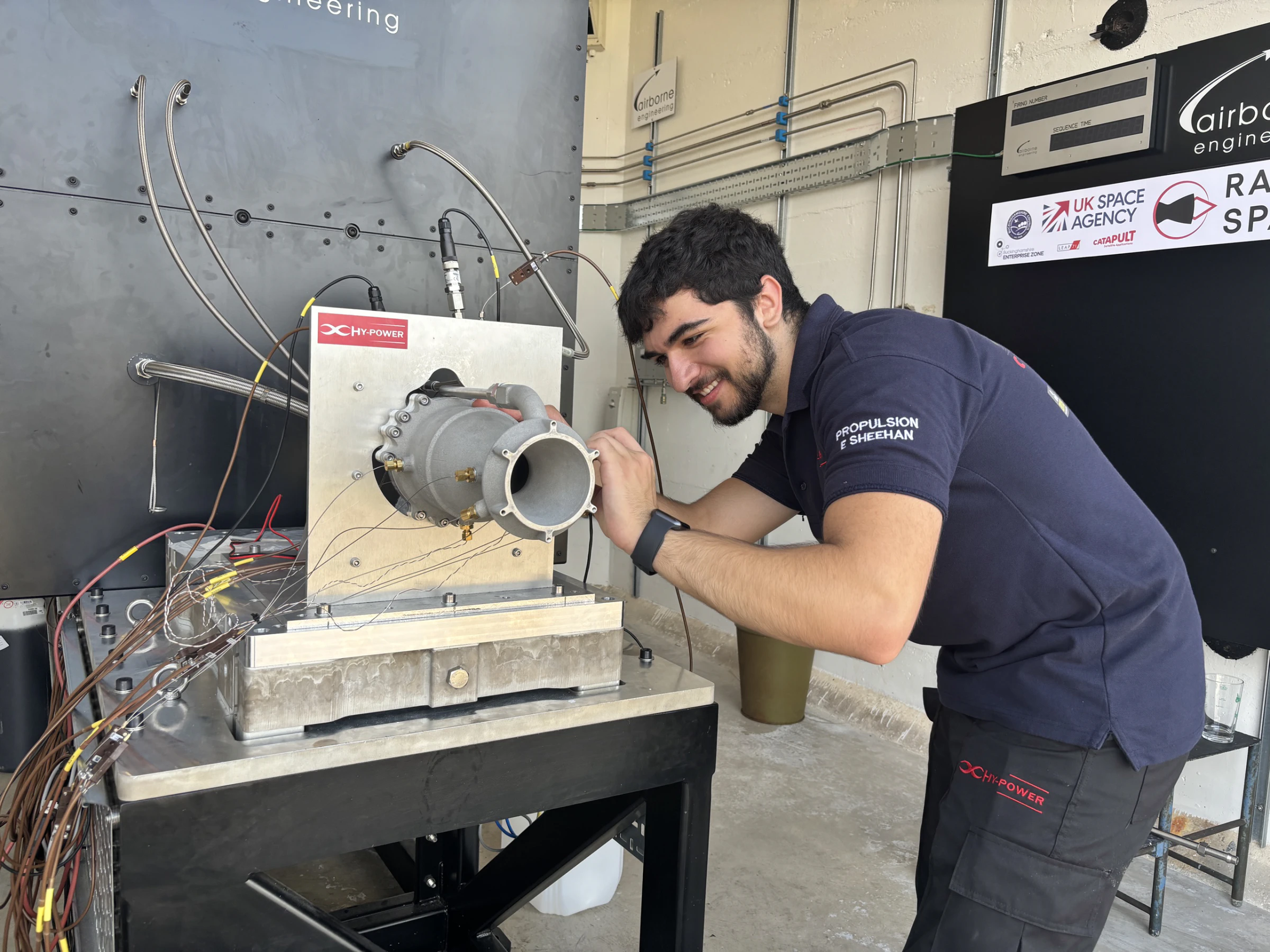
After printing, the chamber had to come off its build plate: a CNC operation on the baseplate. That clip is the one to watch, because it is where the swarf got in. Low-pressure water flow checks passed, since the water flowed around the chips rather than flushing them, so we took the engine to Airborne Engineering at Westcott for Race 2 Space 2025 believing the channels were clean. Installation on the AEL stand, thermocouple wiring and pre-fire marking-up went to plan.
The maiden fire
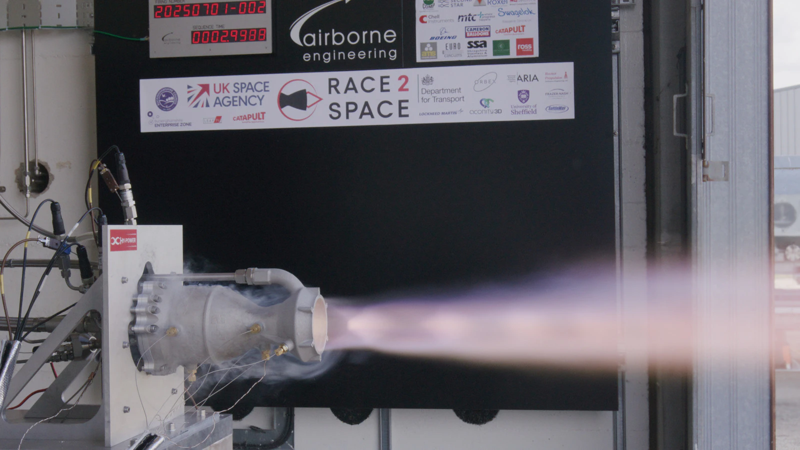
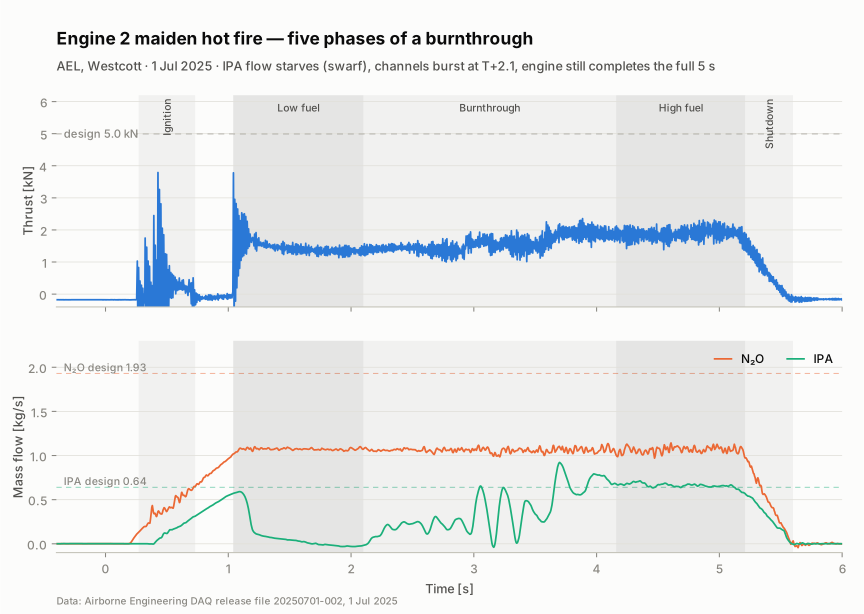
Run 20250701-002, 1 July 2025. The torch igniter lit cleanly by T+0.73 s. Then the fuel collapsed: swarf from the regen channels was driven into the injector and IPA flow fell to about zero, leaving a weak yellow plume at around 1.5 kN. With no fuel moving, all three cooling modes failed at once, film holes blocked, regen coolant stagnant and boiling, no PDMS deposition, while the chamber ran extremely ox-rich. At T+2.12 s the plume turned purple: aluminium burning through the wall as the first cooling channel burst, then more. From T+4.16 s the IPA flow stabilised, the engine settled, and it completed the full 5 s duration.
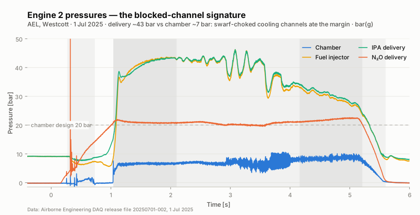
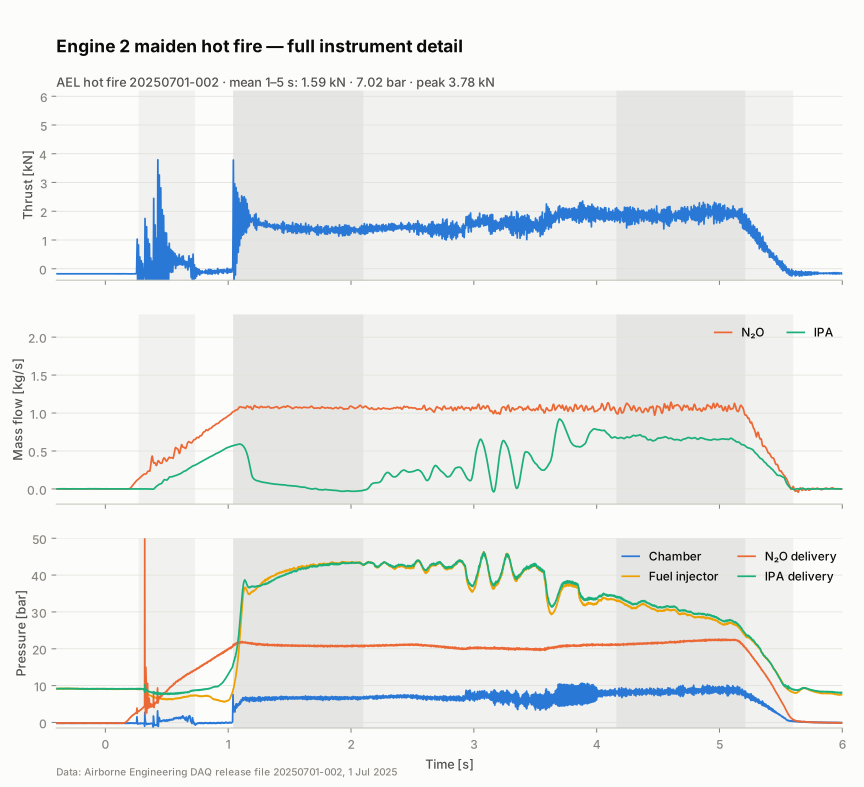
Means over 1 to 5 s: 1.59 kN thrust against 5 kN design, peak 3.78 kN; chamber pressure 7.02 bar against 20; Isp 114 s. Delivery pressure sat near 43 bar with the chamber at 7, the blocked-channel signature. The design point was never reached. The burn-phases plot below replays the DAQ log at the speed it happened: watch the IPA flow starve, the channels burst, and the engine keep running.
Teardown
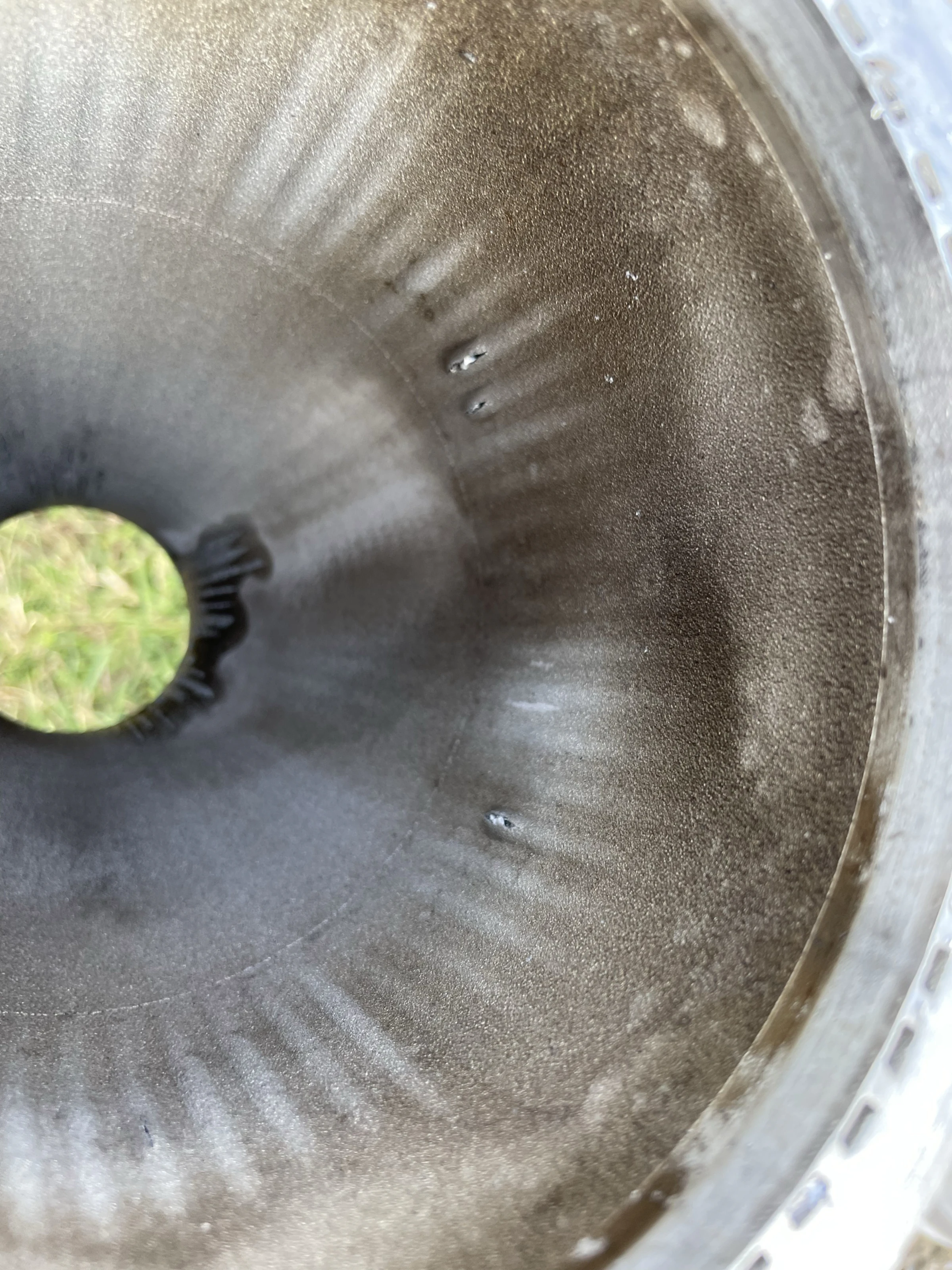
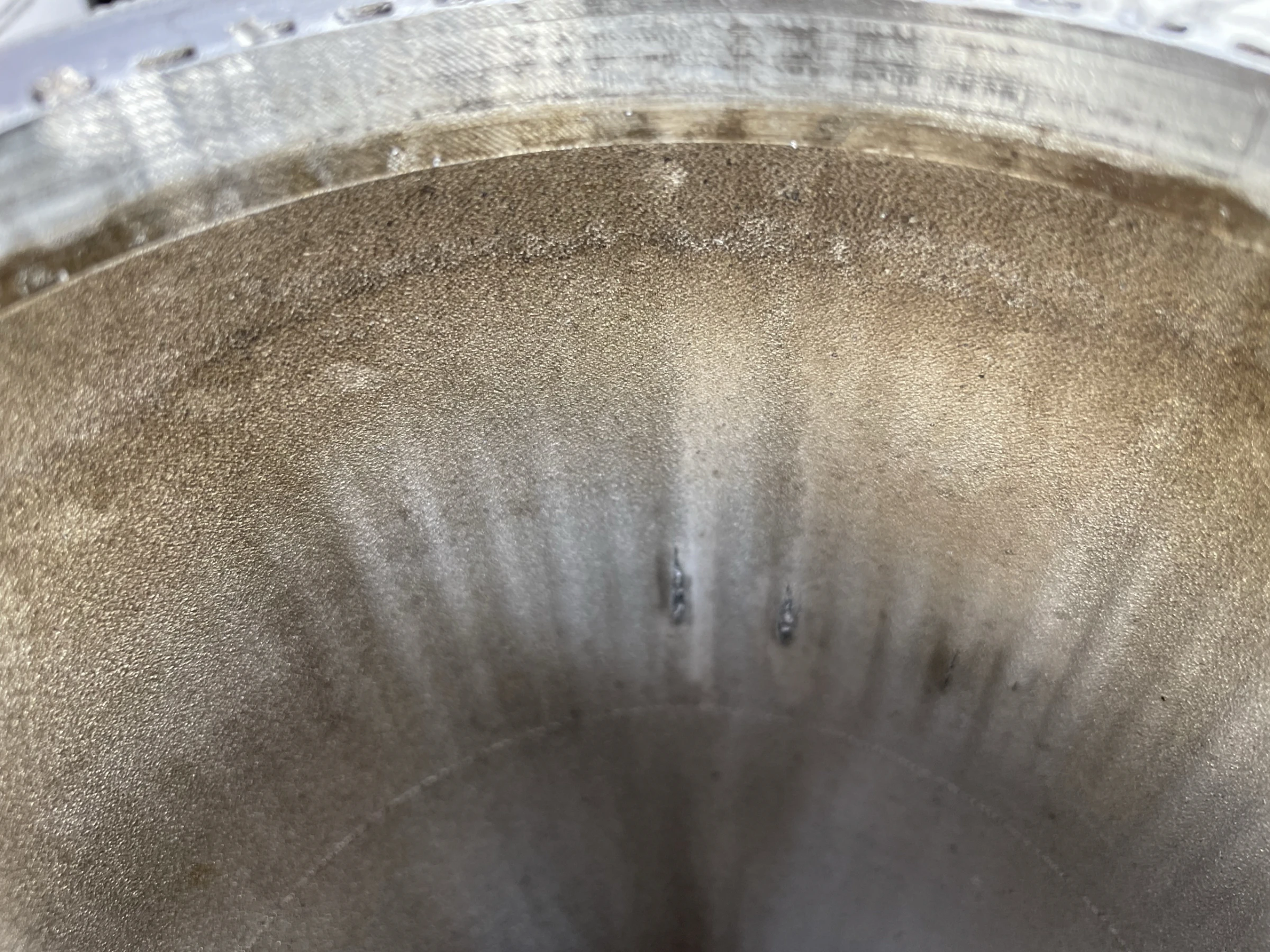
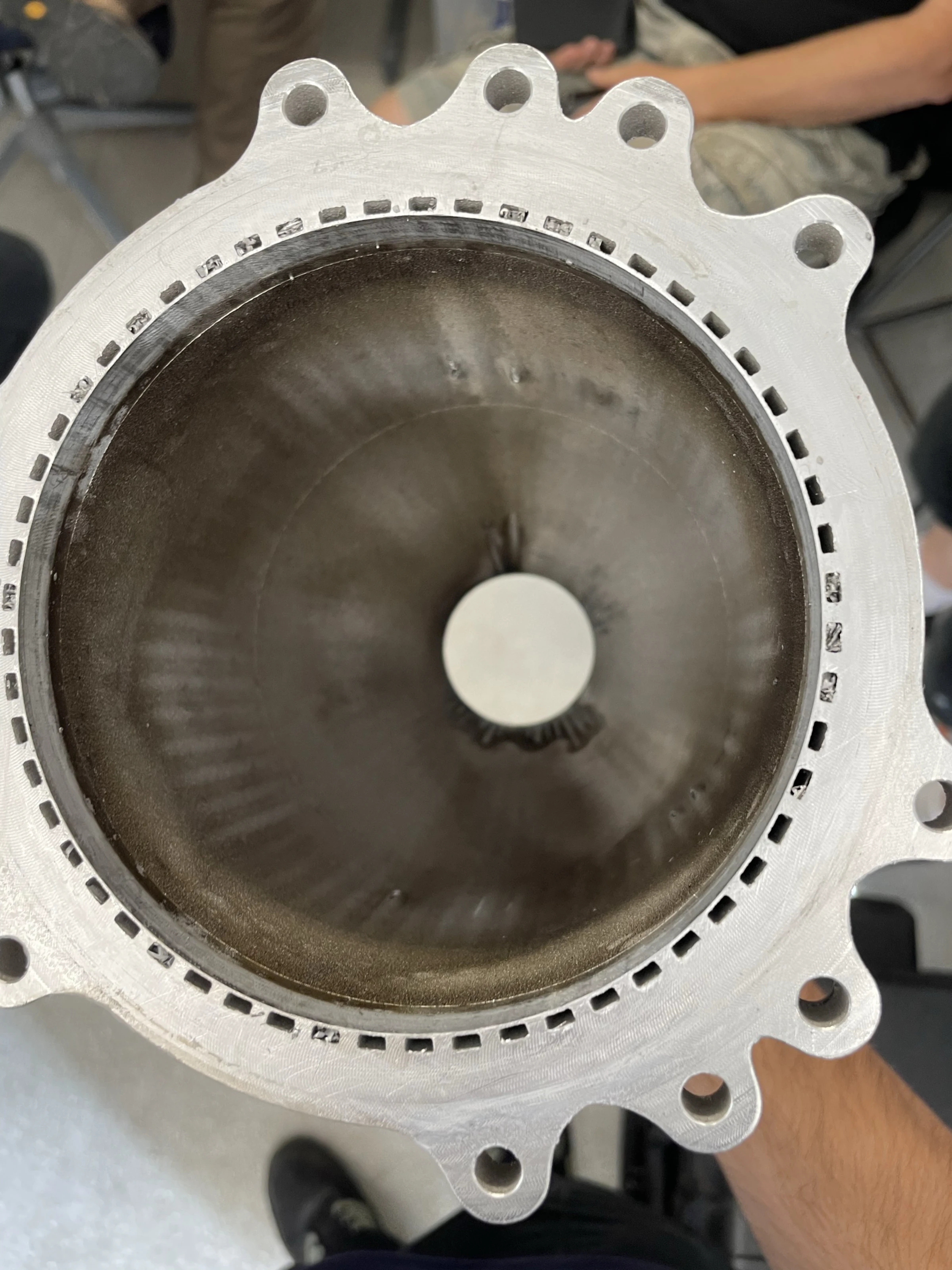
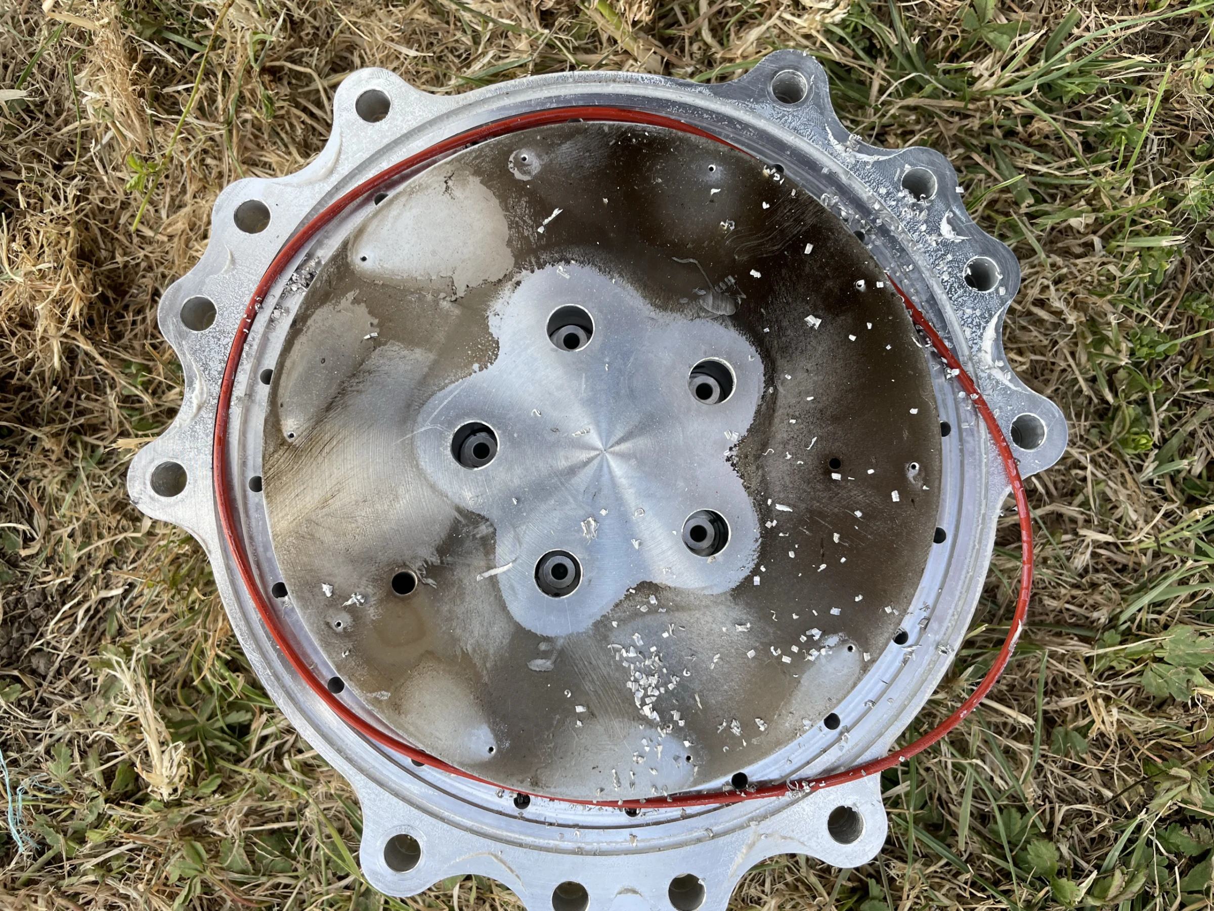
Root cause: machining swarf retained in the regenerative cooling channels, introduced when the baseplate was machined off after printing. Five major channel bursts, plus smaller cracks and bulges in almost every other channel, all sat at one elevation, exactly where the swirl elements sit. The throat had melted. There was no PDMS deposition anywhere. The injector came off full of swarf, piled in the fuel collection manifold and the annular gallery, but was undamaged beyond its O-rings. The water flow checks had flowed around the swarf rather than flushing it.
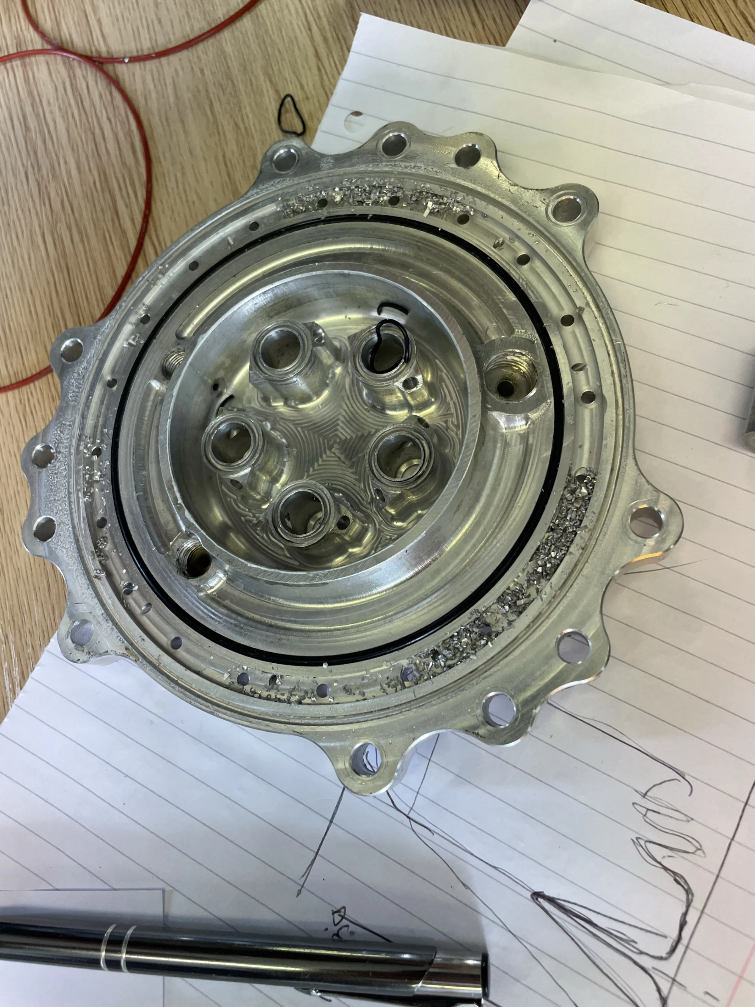
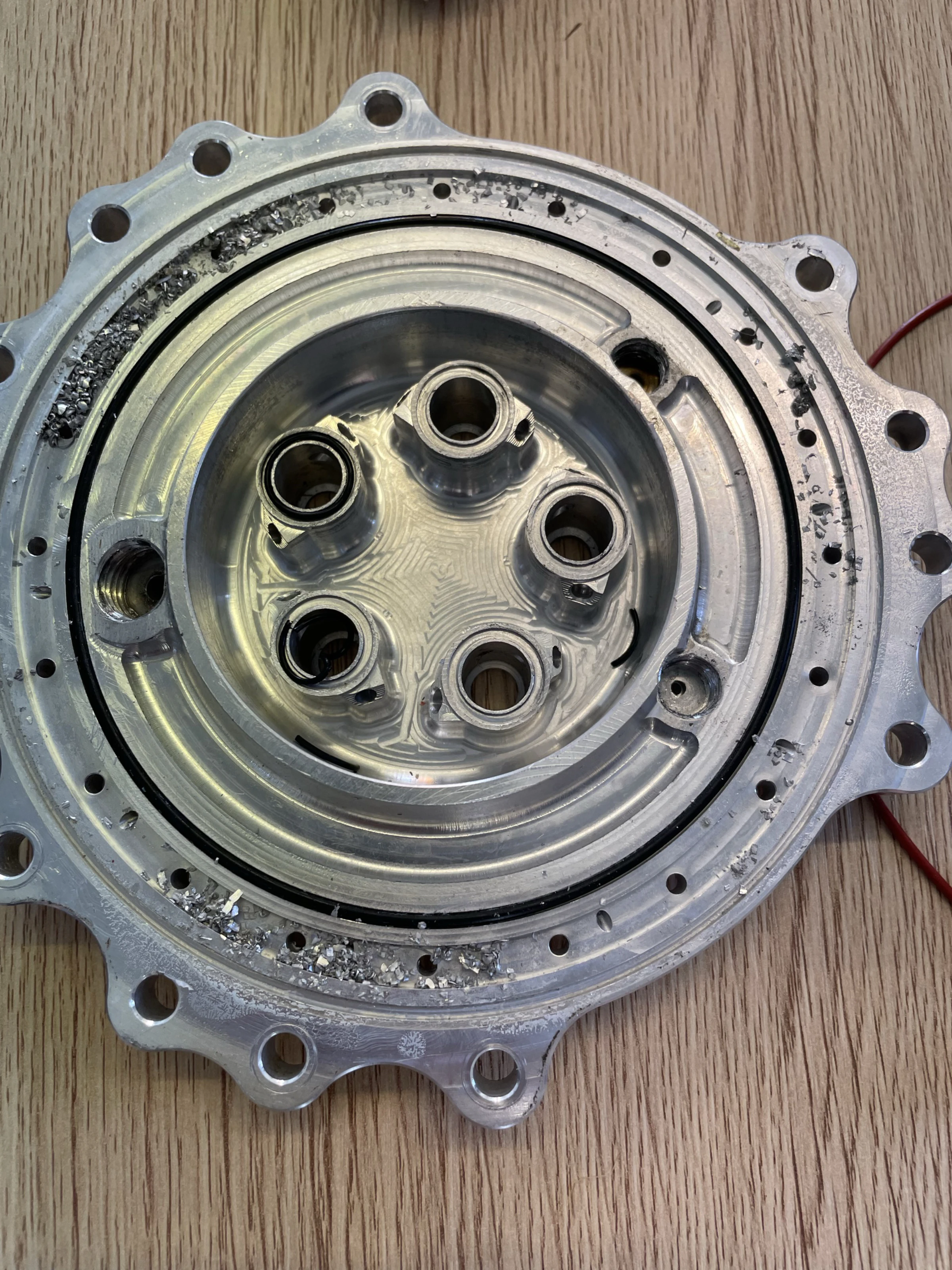
The injector survived
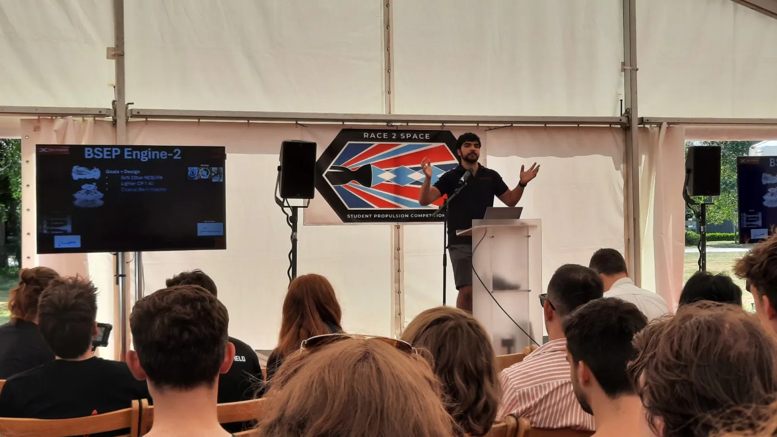
The chamber performed admirably given what it was fed. The coaxial-swirl injector survived and is reusable: its measured N₂O fan angle was about 93°, close to the swirler design prediction, which made a burnthrough the first validation of the coaxial swirl design, under worst-case conditions. I presented the results and the failure investigation at the Race 2 Space 2025 tent. The lessons went straight into Engine 3 and Engine 4.
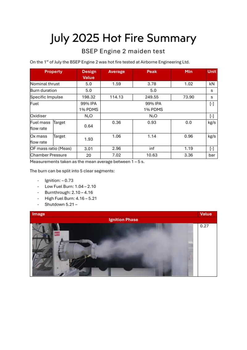 Hot fire testing report — BSEP Engine 2 maiden testThe report the numbers on this page come from: summary table, the five burn phases frame by frame, teardown and root cause.14 pp