AVDASI 2: BlueBird Avionics
Codename BlueBirdAvionics test lead on a six-person team: Hall-effect flap sensing, servo calibration, aircraft integration and three days in the wind tunnel.
A company, not a group
AVDASI 2 is run as a company. Company B traded as BlueBird and was contracted to design, build and test a UAV that could loiter for a long time and land on a short floating airstrip. Wings, fuselage, pod and empennage each had their own team; Team 18 was avionics, six of us, responsible for every wire, sensor and line of ground-station code on the aircraft. I was the avionics test lead, which in practice meant I owned integration and calibration: making the other teams’ structures move, and proving they had moved by the angle we said. In the technical report I wrote the integration and aerodynamics sections and the executive summary.
A magnet on the flap spar
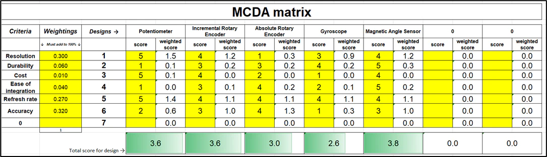
The customer wanted flap position measured independently of the servos, so reading back the PWM you had just commanded was not good enough. Máté led a down-selection across rotary encoders, potentiometers, gyroscopes and Hall-effect sensors: criteria cut to six by vote, weighted by pairwise comparison, then scored in an MCDA matrix. Magnetic sensing won on accuracy, resolution and refresh rate, and the report claims it as the first time it had been made to work in this unit.
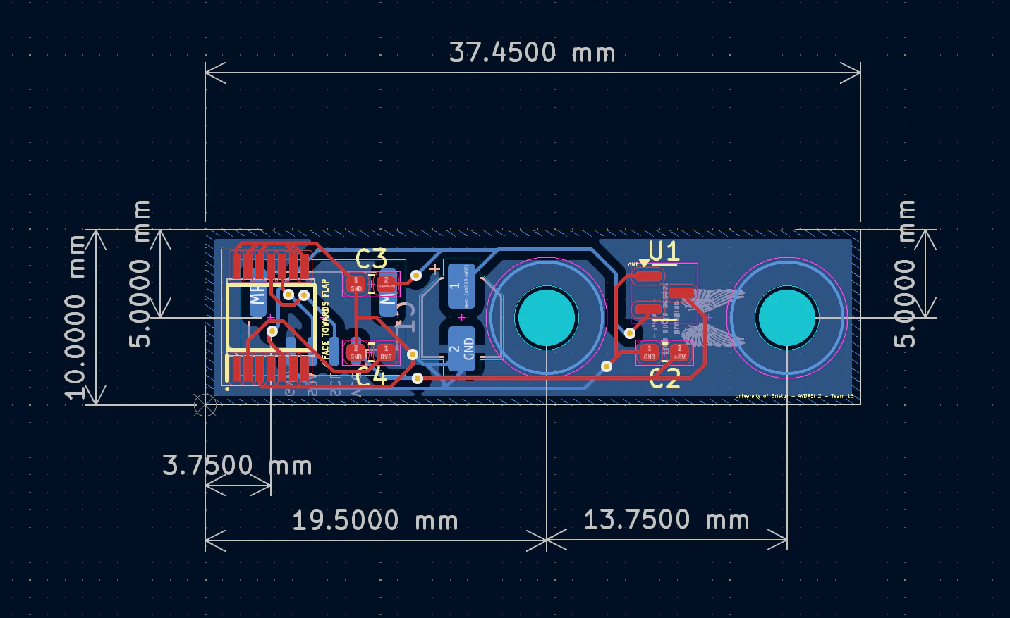
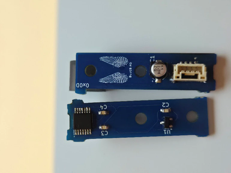
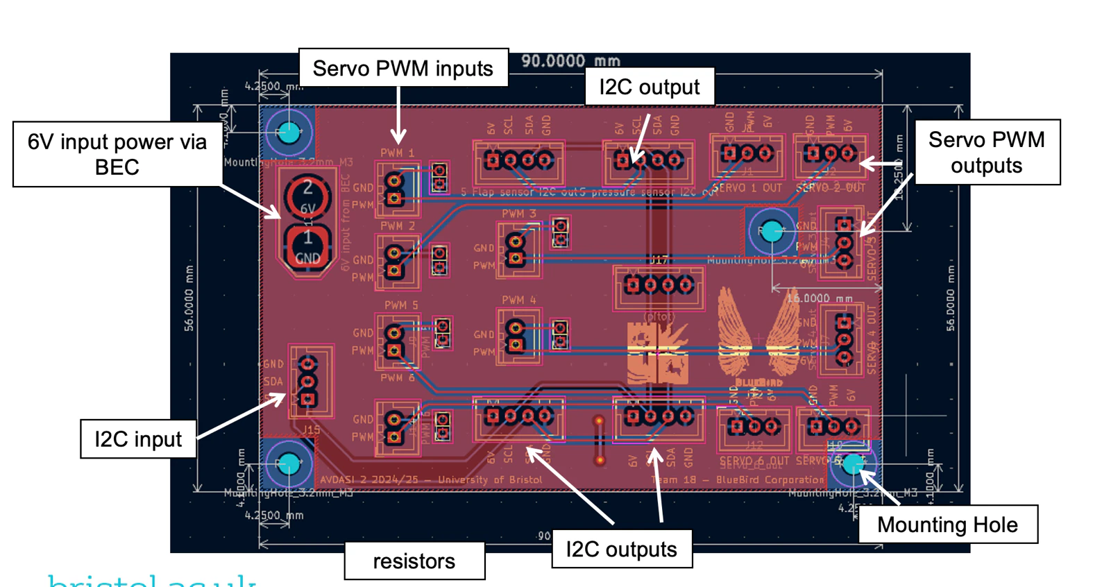
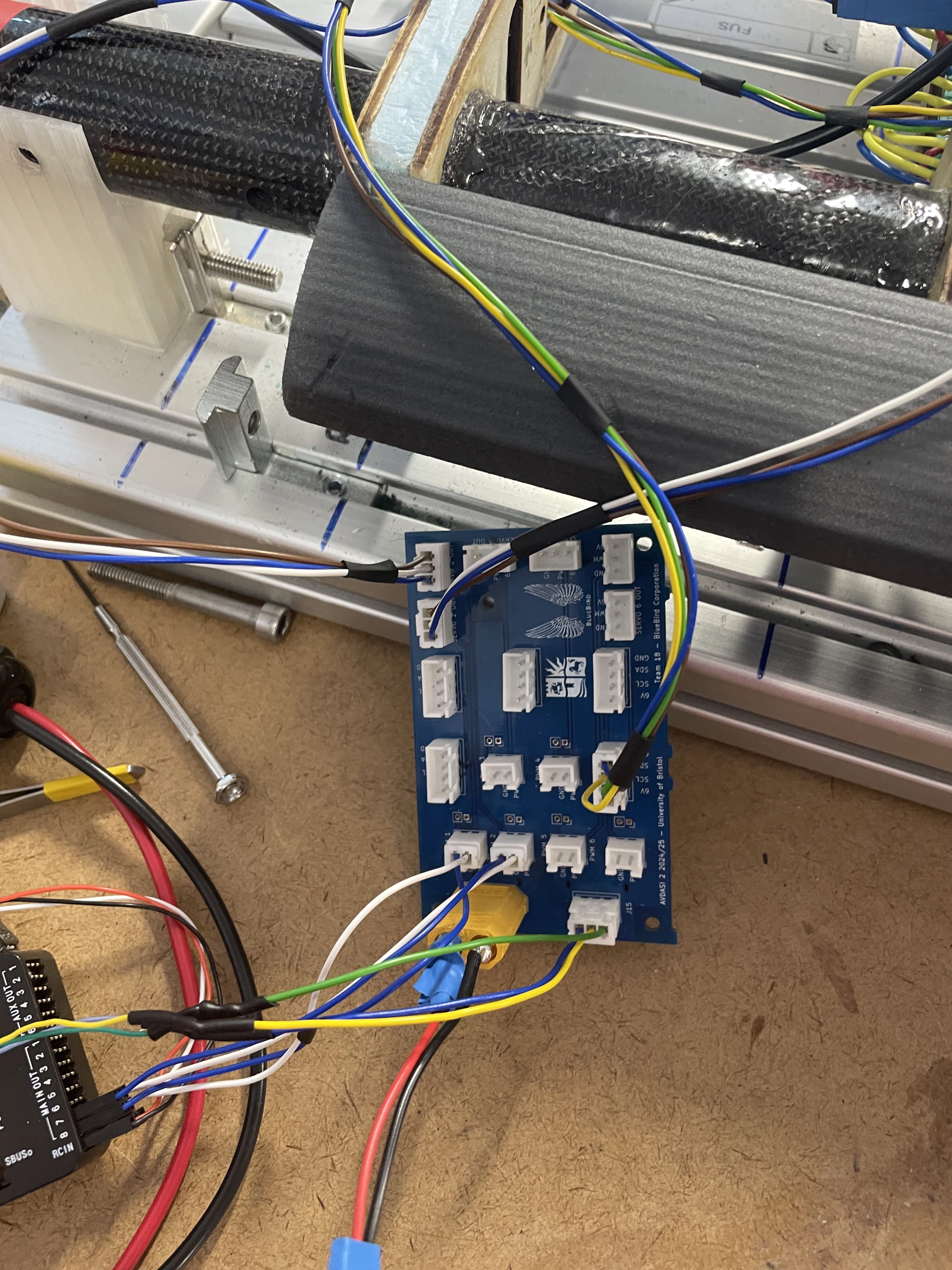
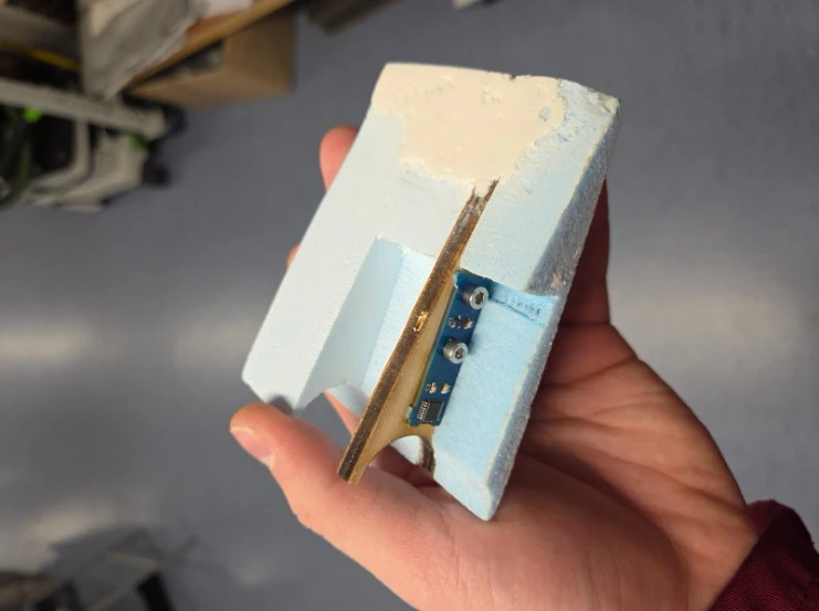
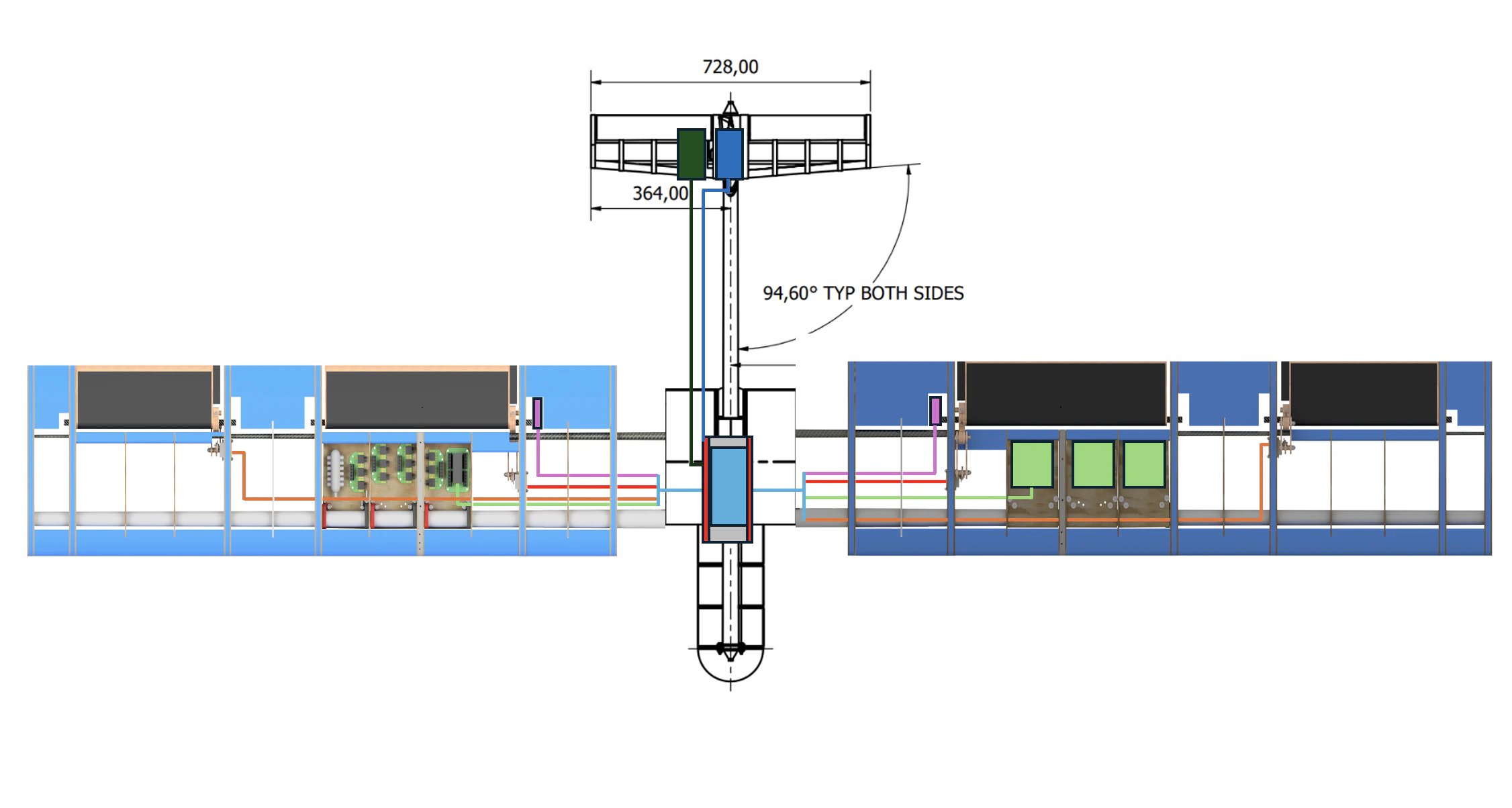
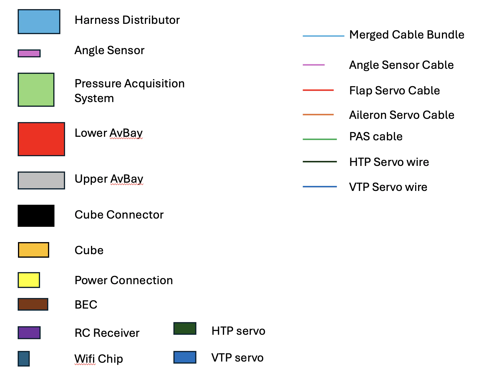
The board is 37 by 10 millimetres so it fits between rib and skin, ordered bare from JLCPCB and hand-soldered. It reads a magnet epoxied to the flap spar itself, which is the whole point: it measures what the flap actually did. The harness distributor is the other board we made. It feeds the Cube, both power modules and the servos from a single 7.4 V input, and it exists mainly so that nobody can plug the aircraft together in the wrong order.
Three steps to one degree
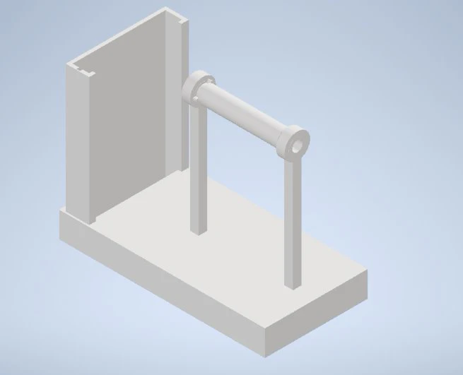
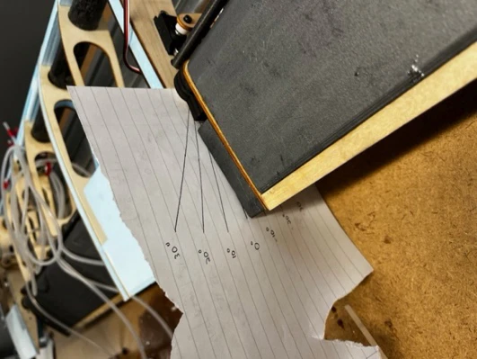
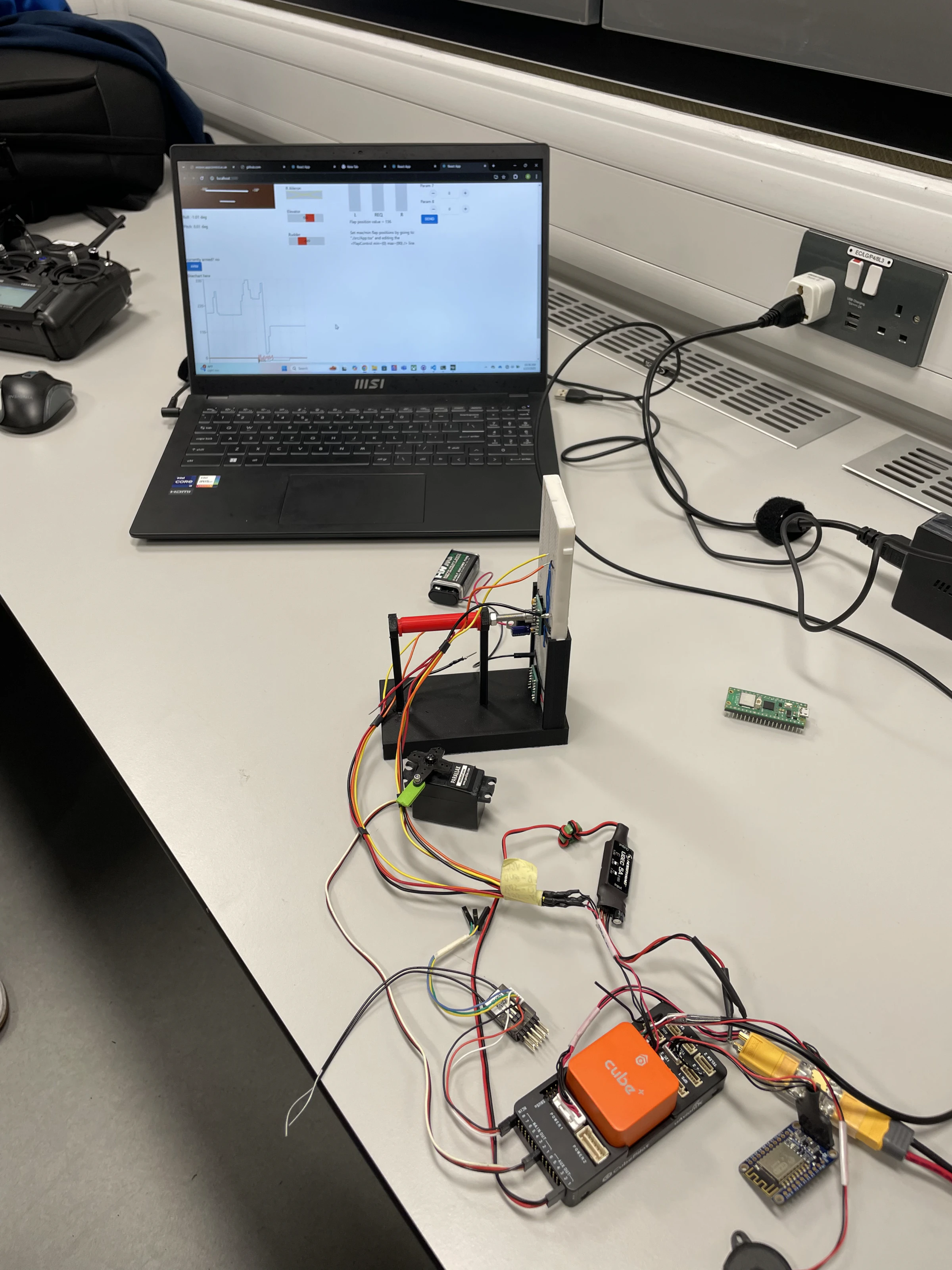
Control surface deflections had to be accurate to a degree, and servos do not come that way. I built the calibration as three steps. First a servo tester, straight after the mechanisms were built, to prove each servo could reach the angles asked of it and to find the bad ones early. Then a custom calibration circuit that mapped deflection angle to PWM: find the maximum and minimum, record their pulse widths, take a few points in between and fit a line. Then the equations went into the telemetry code and got a final trim against an electronic level. The middle step was the useful one, because a mechanism team could change something and I could re-derive their equation the same afternoon rather than re-doing the whole chain.
Integration was the hard part
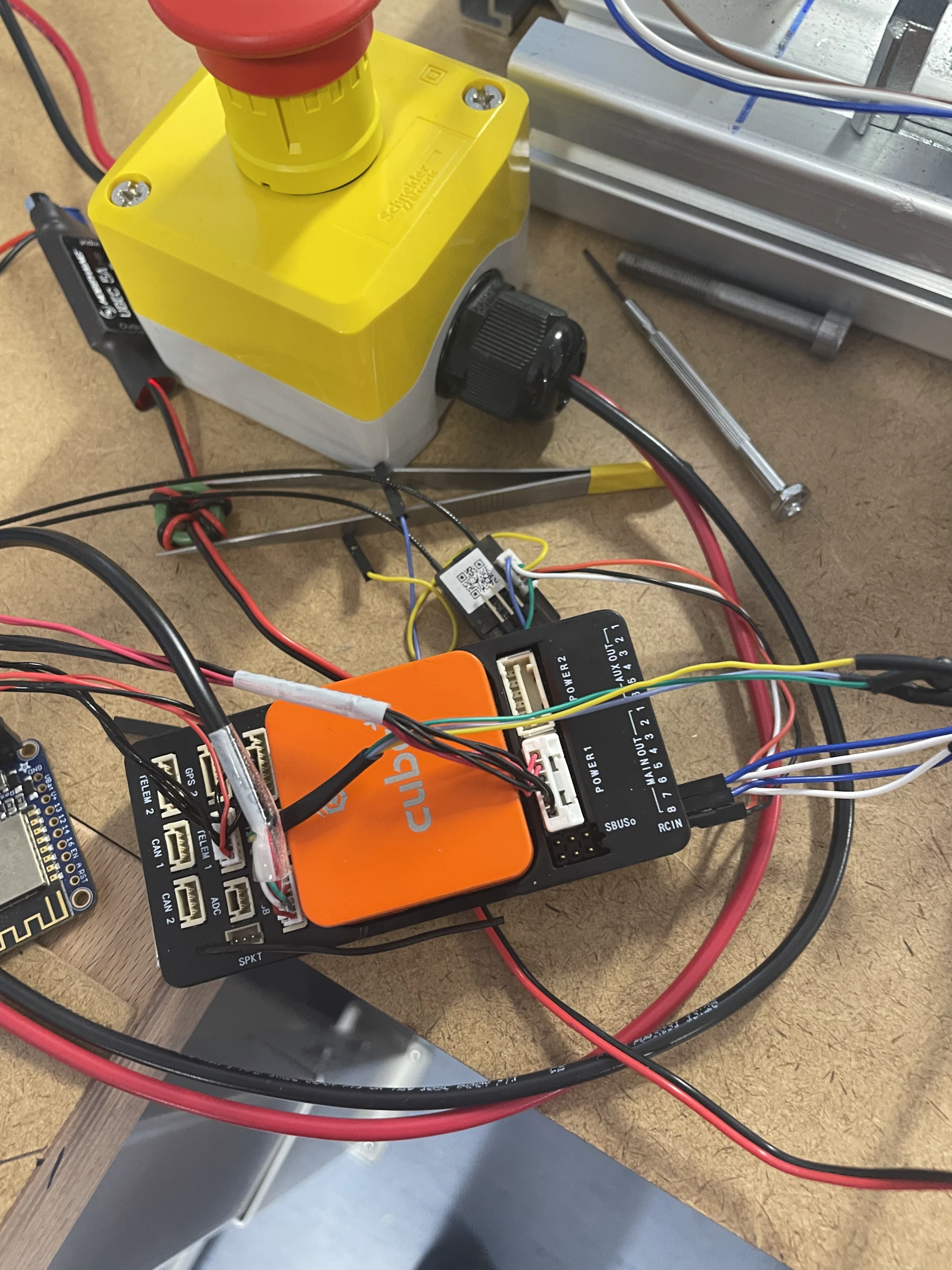
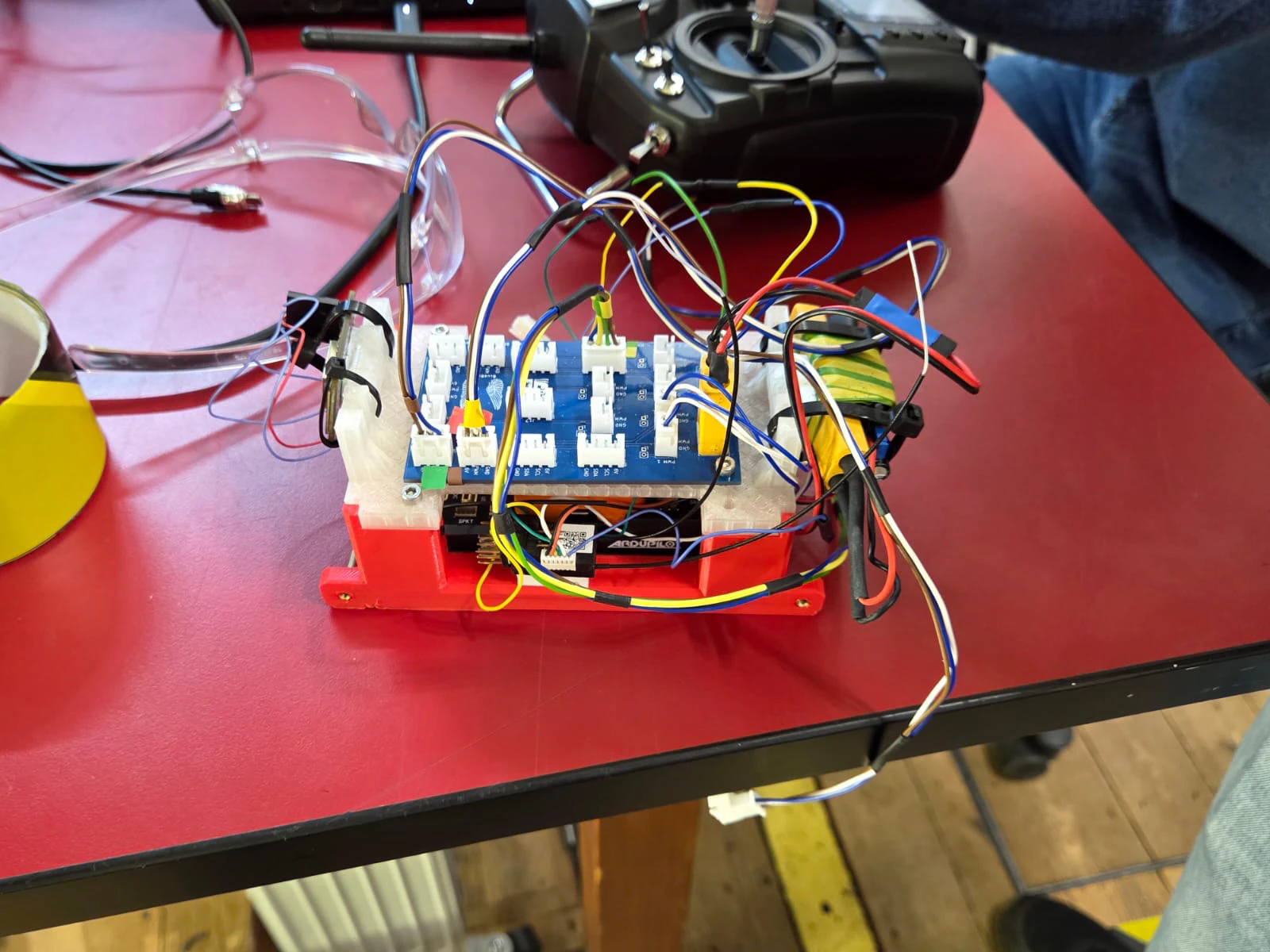
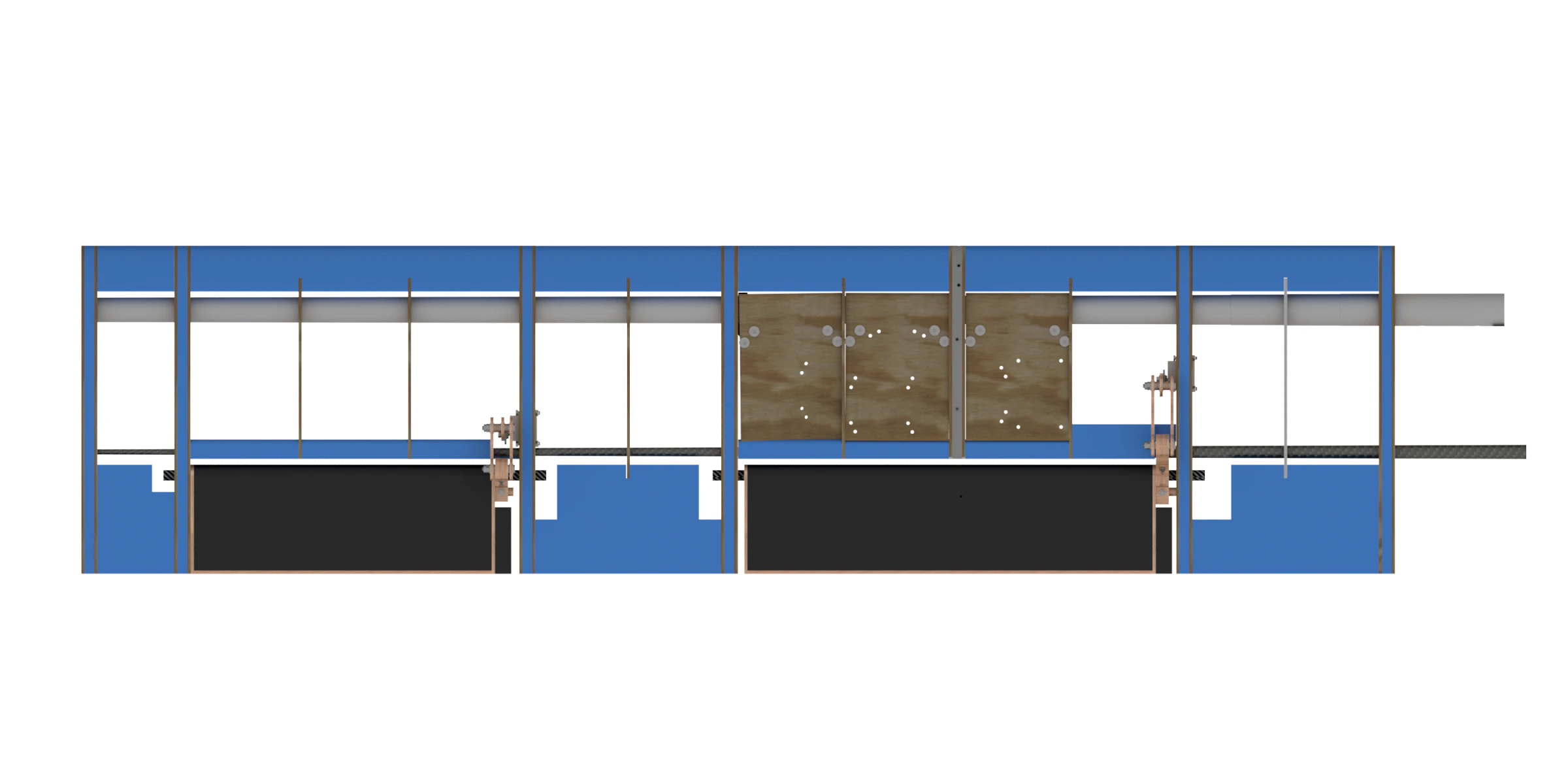
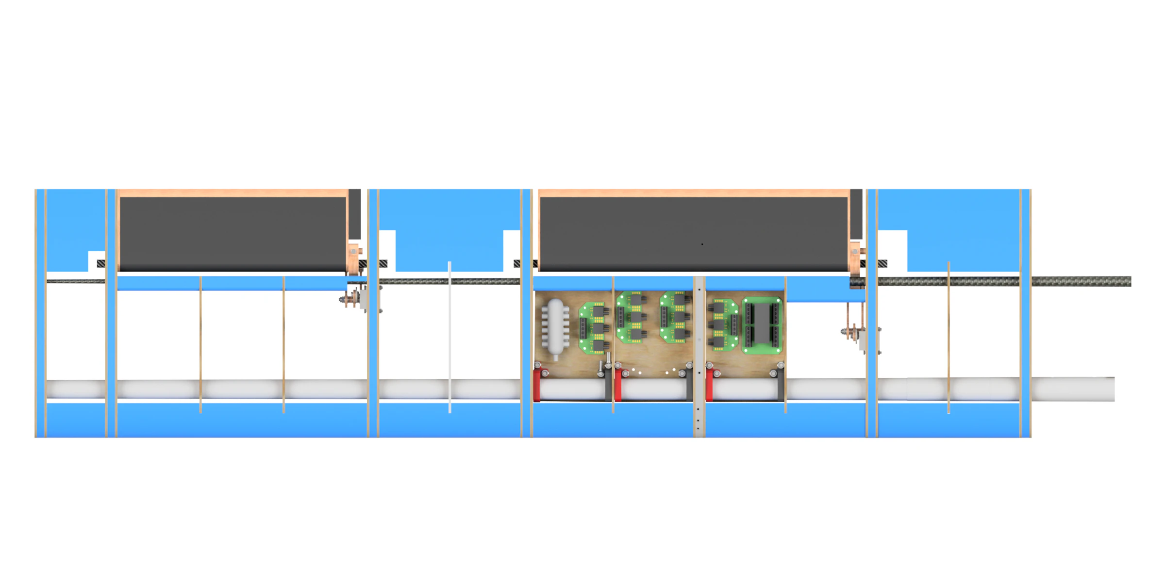
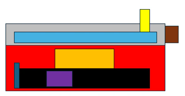
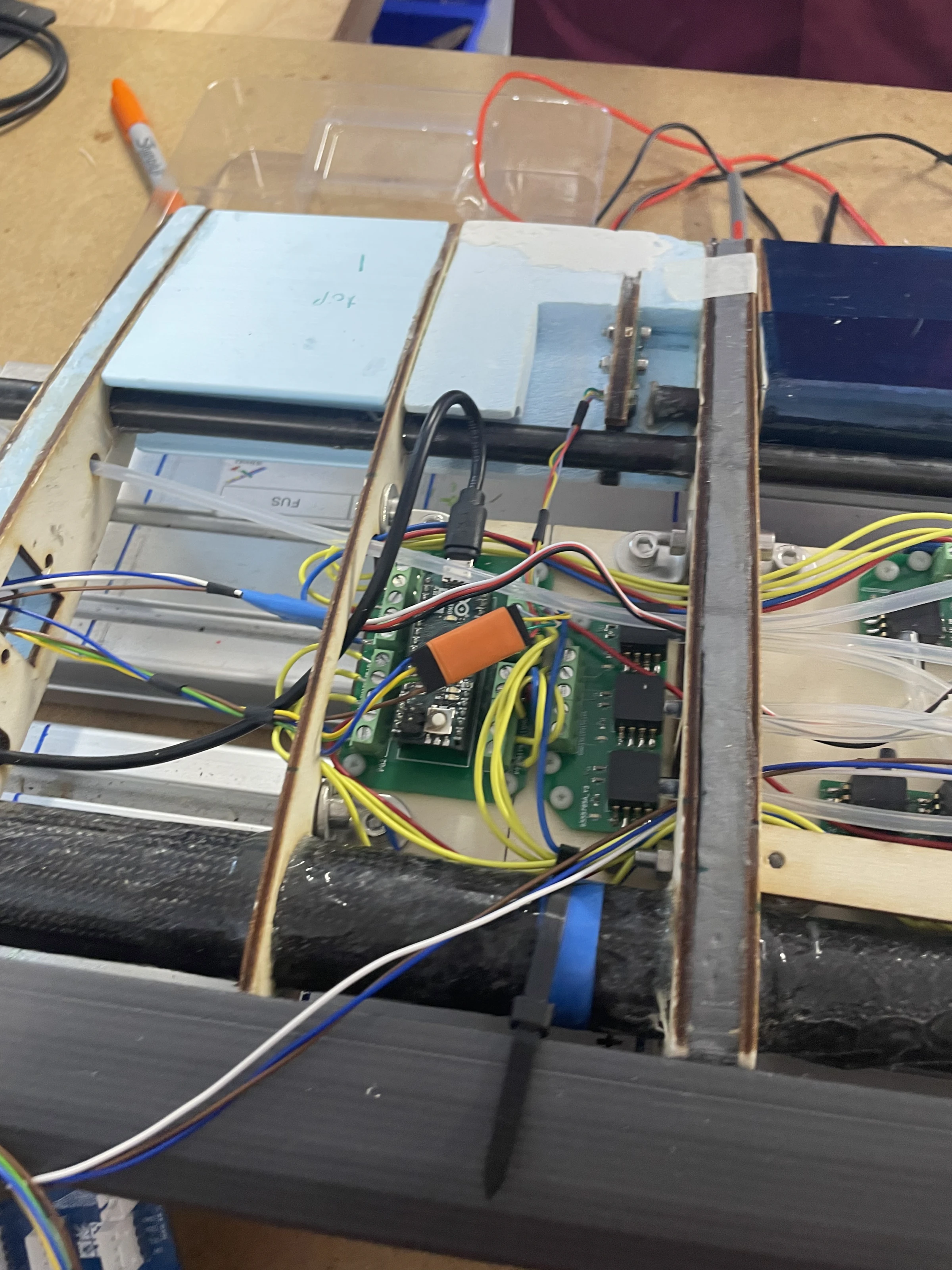
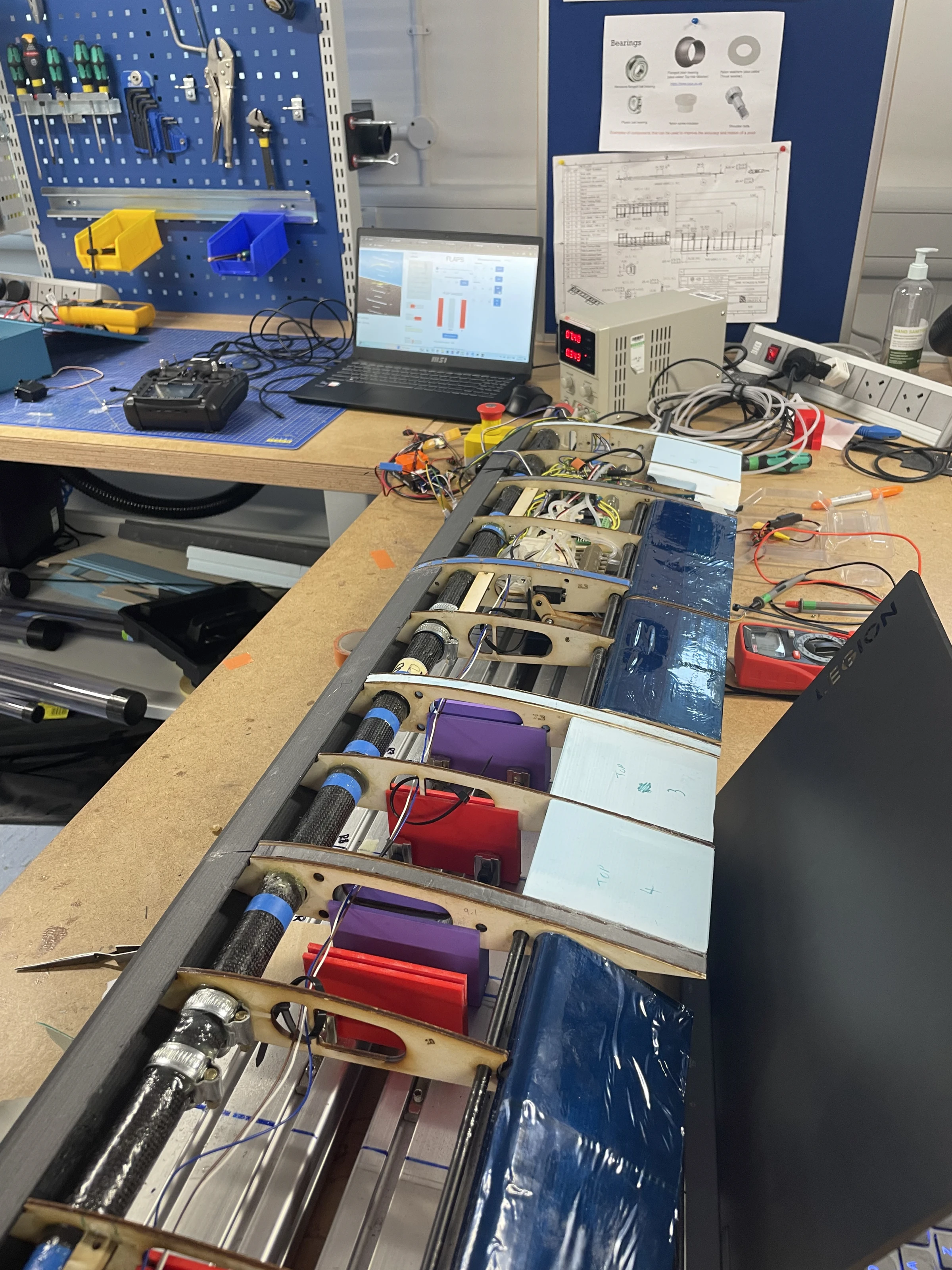
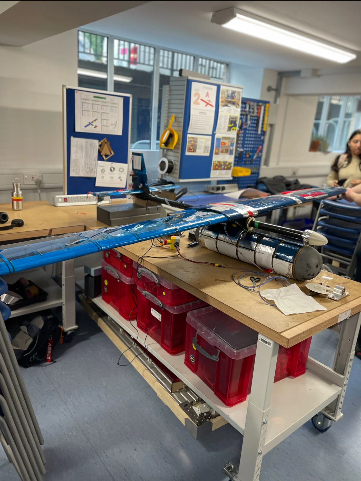
Integration was the most difficult part of the project and the part where other teams’ slippage landed on us. The pressure system was designed as a self-contained box because that made it trivial to install; by the time the wings were real the boxes would not fit and could not be shrunk, so it became boards screwed to plywood floor panels, designed by us and then handed to the wing teams who knew how to get them inside. The pod team gave us two aluminium plates in the roof to mount to, which turned out to be almost impossible to work in, so we designed and printed a two-part avionics bay that bolts into the payload deck instead: Cube and radios in the lower half, harness distributor and power modules in the upper.
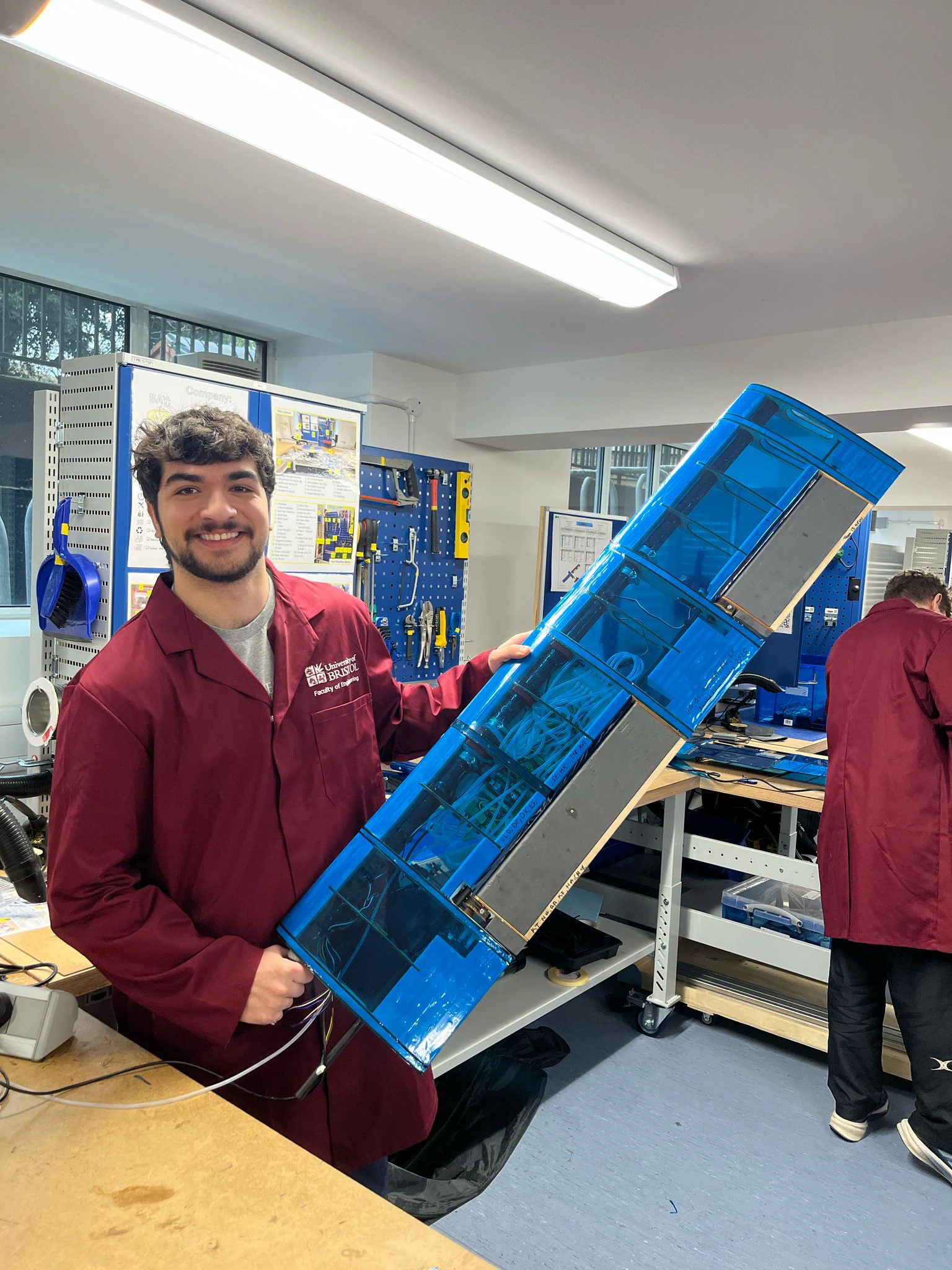
On the starboard wing the rib that should have carried the sensor was glued to the spar before the mounts were machined, so the mount was drilled by hand and some trailing-edge foam came out, supervised by the wing’s structures people. The sensor itself was the one thing that went in as planned — a rib, a magnet on the flap spar, and one trim with a Stanley knife.
Three days in the tunnel
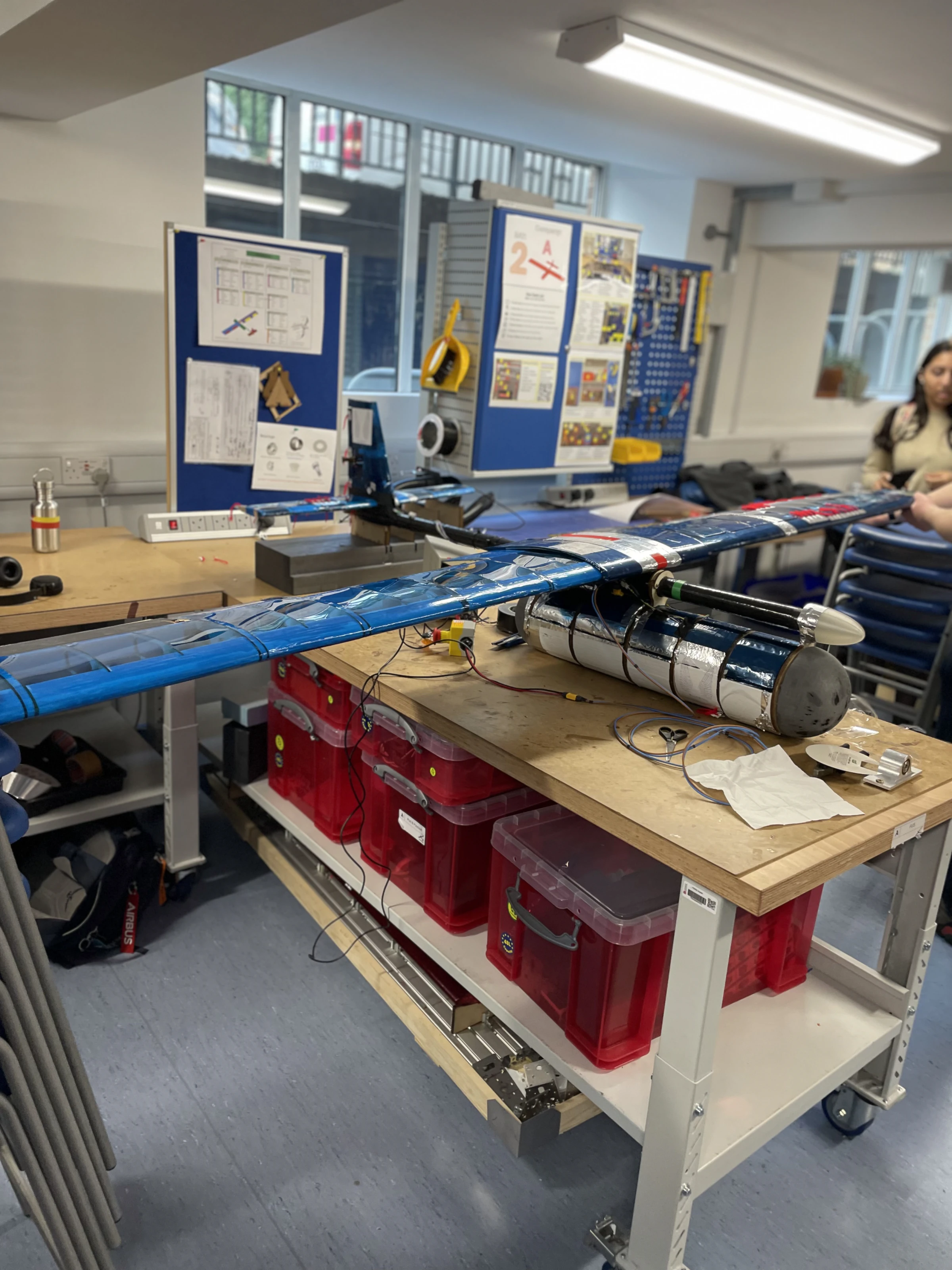
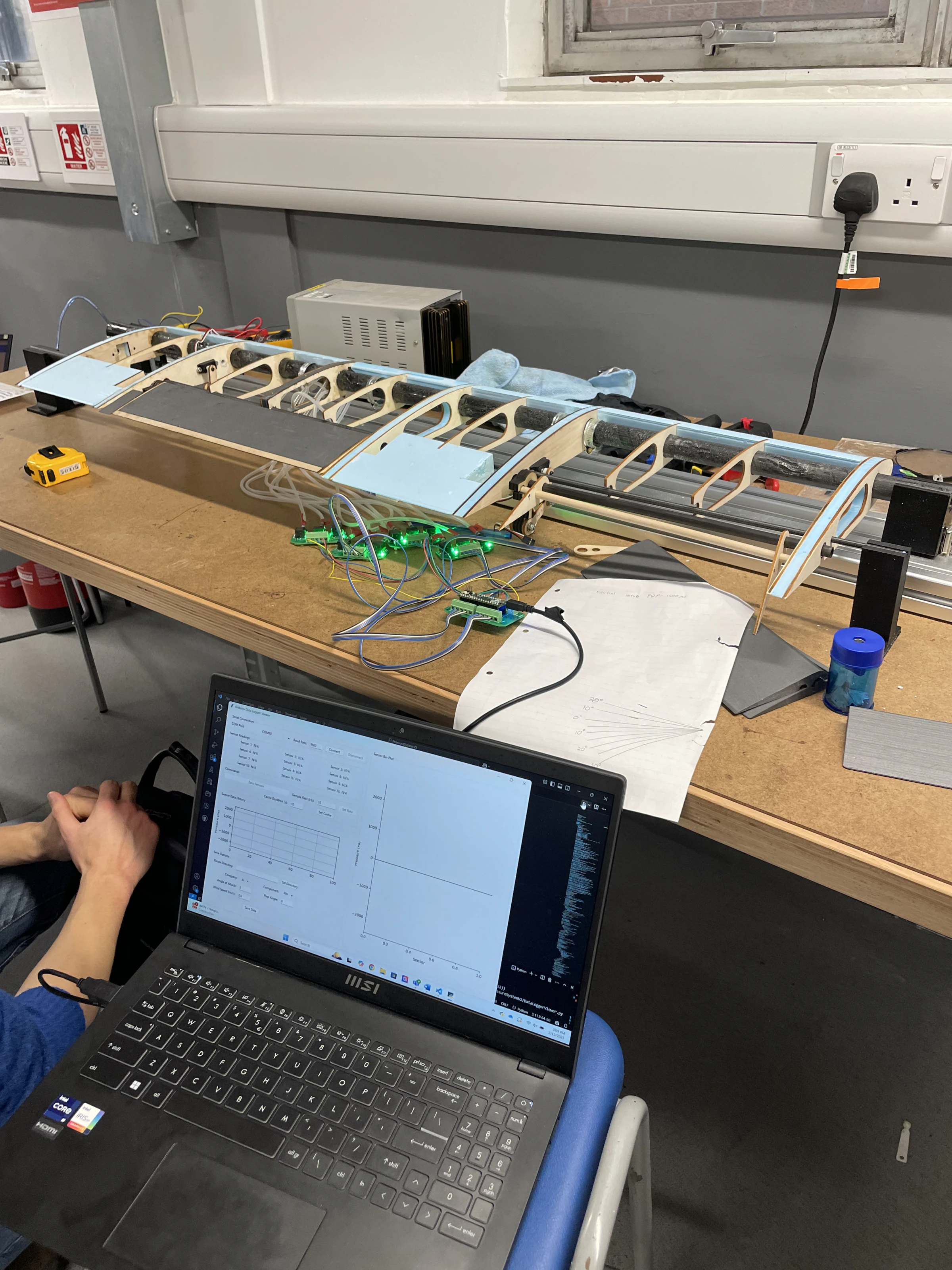
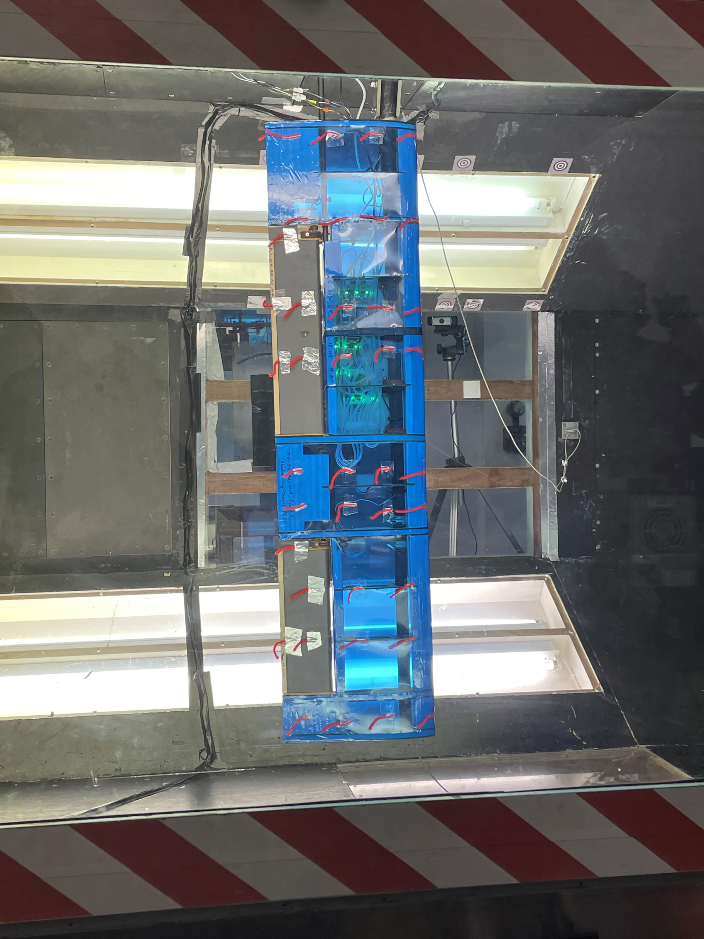
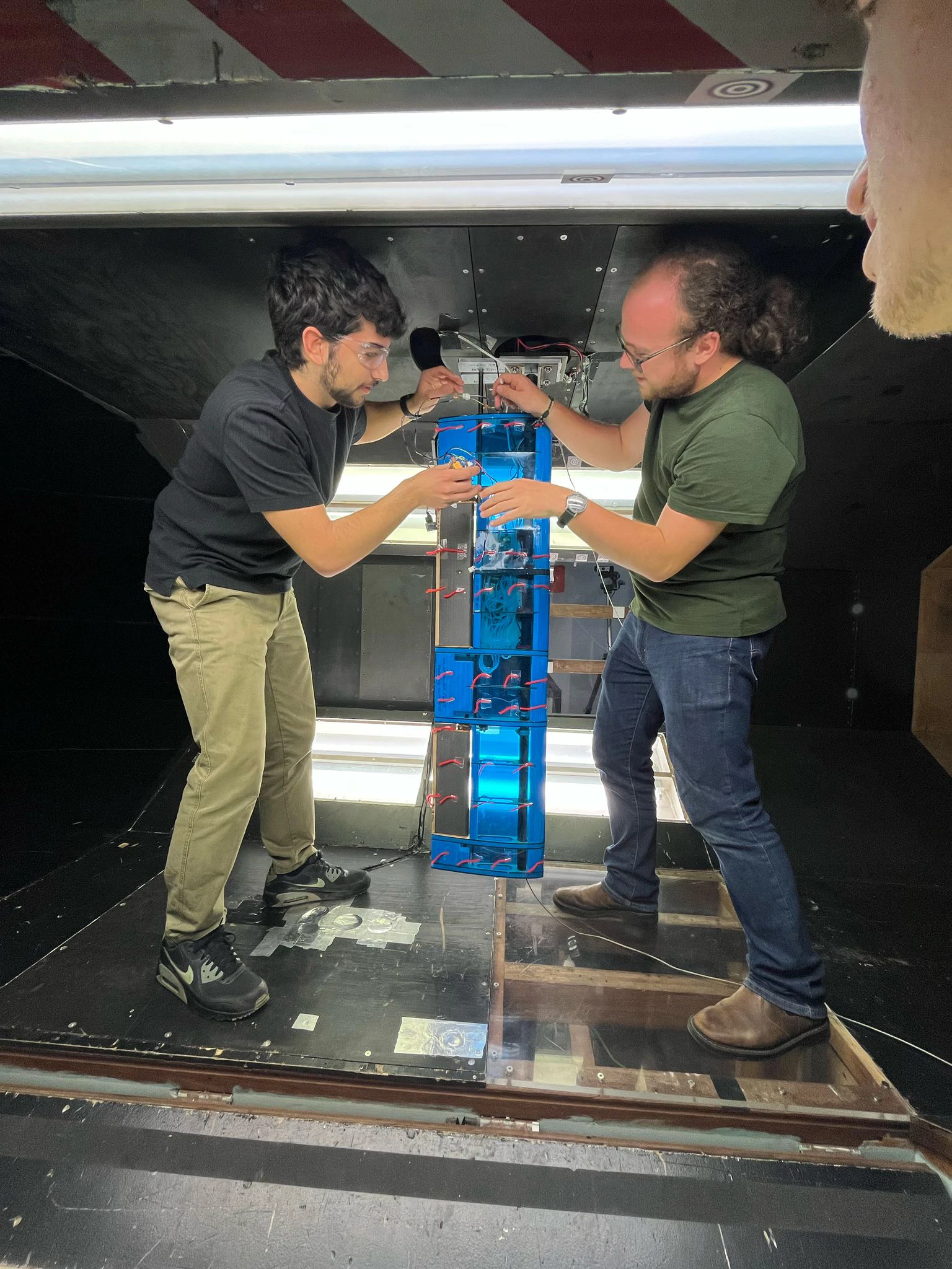
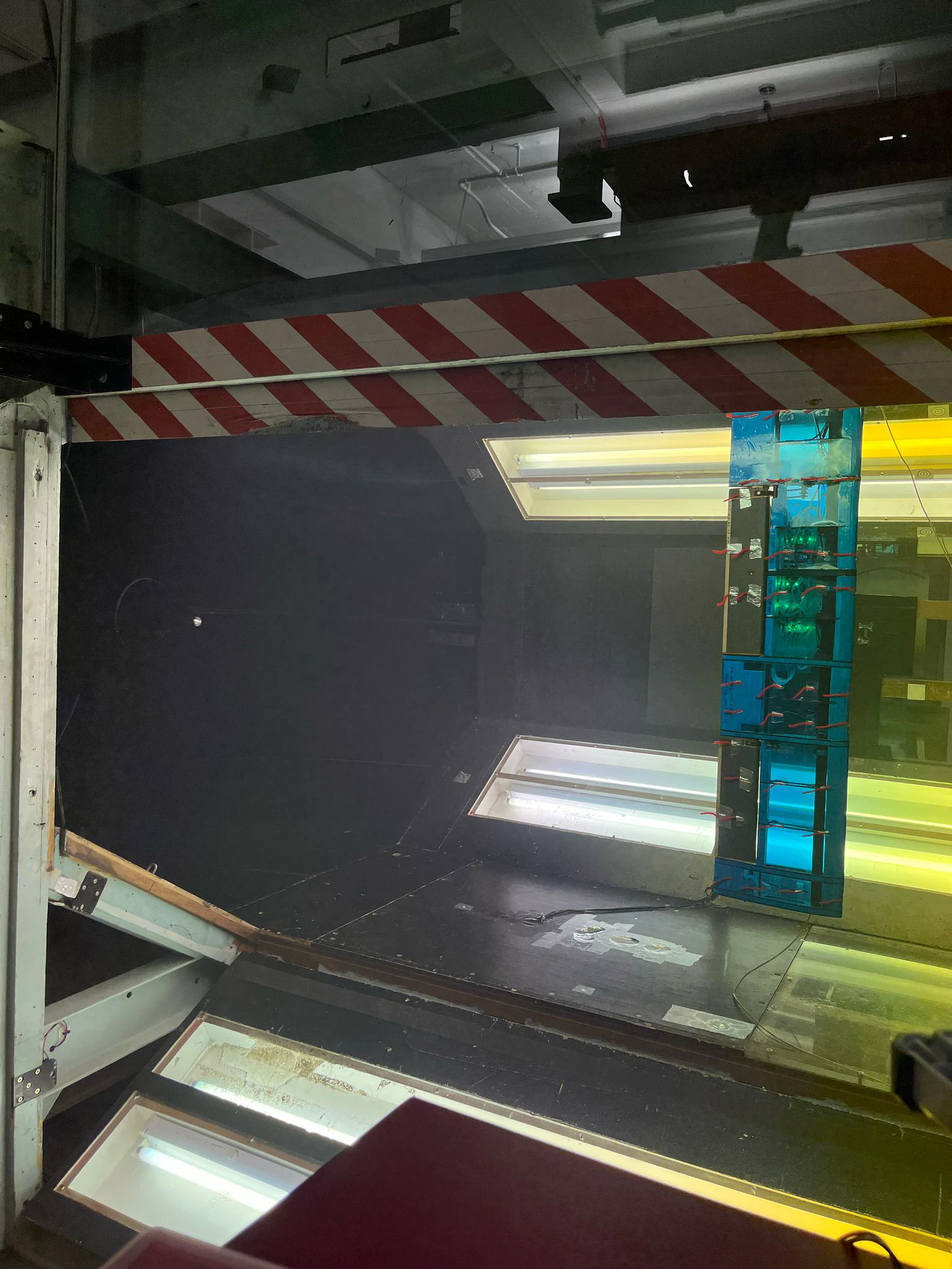
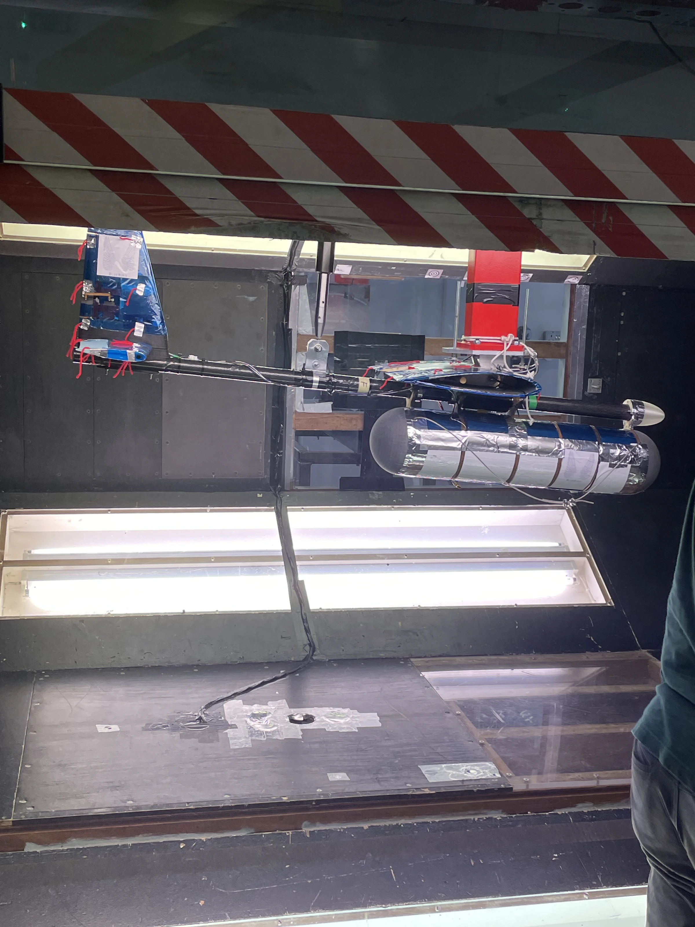
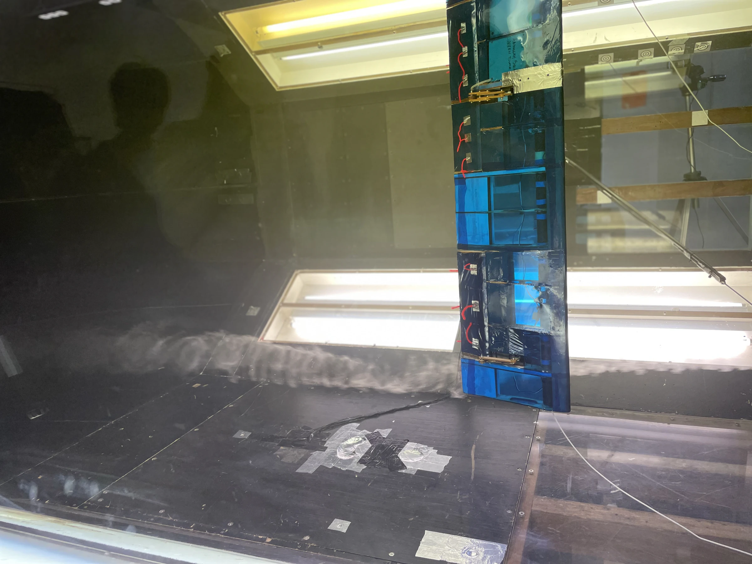
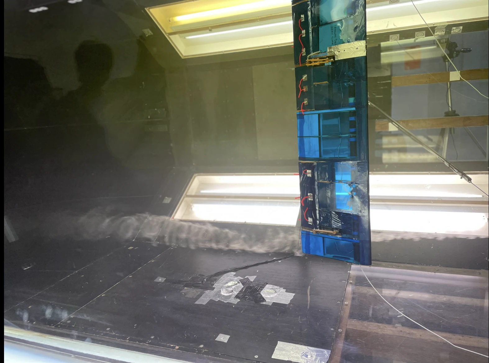
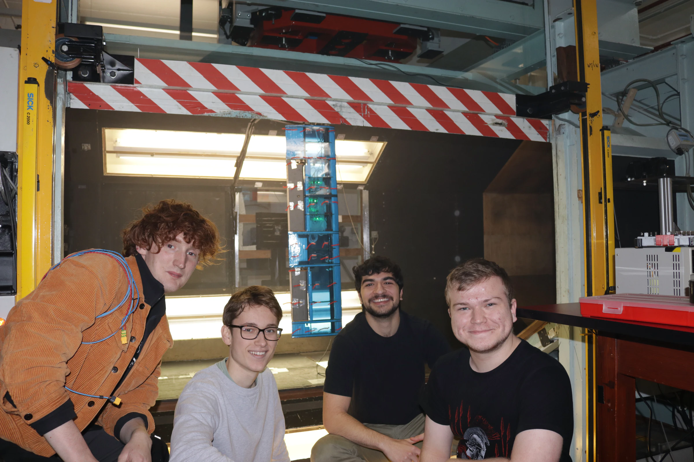
Starboard wing on 21 February, fuselage on 24 February, port wing on 26 February. The wing goes into the tunnel on its own, vertically, tufted with red wool so you can see where the flow lets go; the green glow through the film is my sensor boards reporting flap angle while the tunnel runs. Nothing in the software needed intervention across the campaign, which is the sentence I am most pleased with in the whole report.
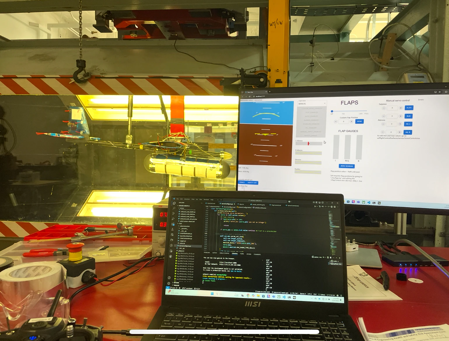
The two failures were ours and small. The user interface leaked memory and got laggy after a few minutes, so we refreshed the page when it did. On the last run all three processes were being run from one editor, and pressing run on the telemetry system silently killed the interface — a start-everything script would have cost half an hour and saved that.
Predicted against measured
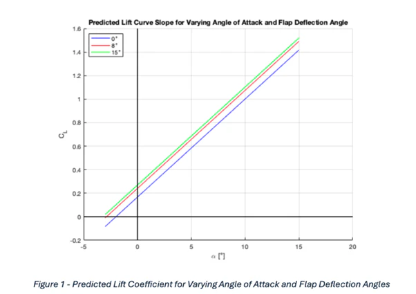
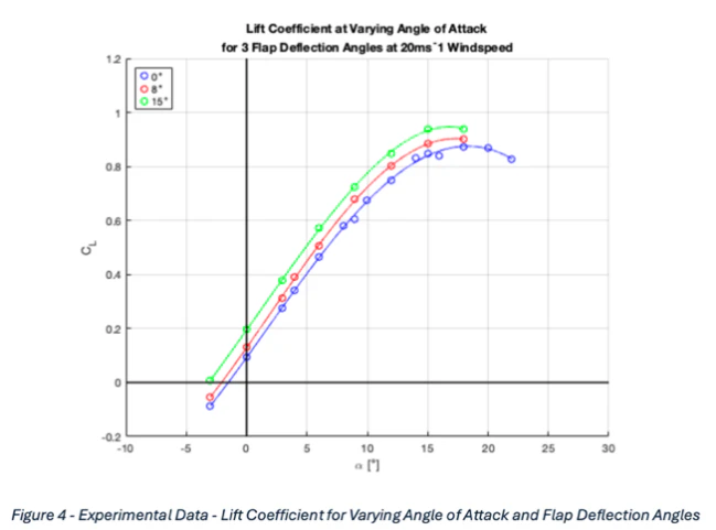
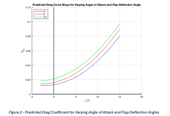
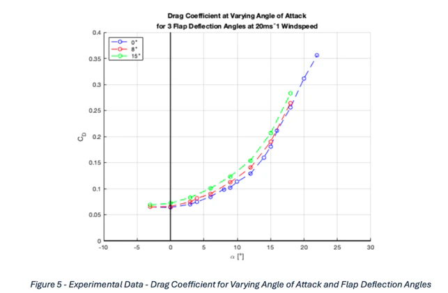
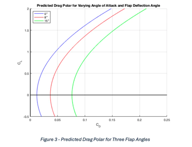
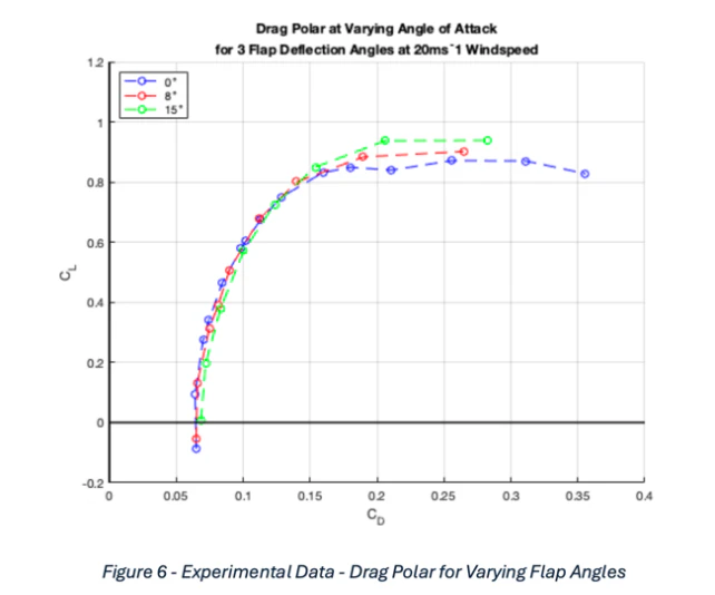
The aerodynamics section is the comparison: predicted coefficients against what the tunnel actually gave, for flap deflections of 0, 8 and 15 degrees at 20 m/s on the NACA 2415 section. The lift curve does what it should — linear at low incidence, rolling over around 15 degrees, and stalling at almost exactly the angle predicted, which is the one clean win. Everything else is worse than predicted: peak lift coefficient near 0.95 against a predicted 1.5, zero-lift drag around 0.065 against roughly 0.015 predicted, and drag polars that cluster together instead of separating with flap angle.
Across most metrics the wing came in 20 to 40 per cent below prediction. Some of that is manufacture — surface finish, film folds on the underside of the leading edge, cavities that let flow into the skin. The largest single contributor is almost certainly the flap mechanism, which protruded further than it needed to and was bulky enough to interfere with the flow properly. Streamlining it would have cost rigidity, which is the trade nobody made because nobody had costed the drag.
One degree on the bench, one to three in the tunnel
On the bench and at the Gate 4 inspection the flap sensors held the degree they were designed to. In the tunnel they drifted to one to three degrees. Two reasons, both traceable. The wings vibrated hard enough to push the magnet off the sensor axis; damping in the wing would have helped, and so would a stronger magnet, because then being off-axis matters less. And the magnet was not the one we specified — the neodymium sensing magnets did not arrive in time, so ordinary ferrous button magnets went in against the deadline, which made the vibration sensitivity worse. It is a shipping-lead-time failure dressed up as a sensor failure, and it is the thing I would fix first.
Paper trail
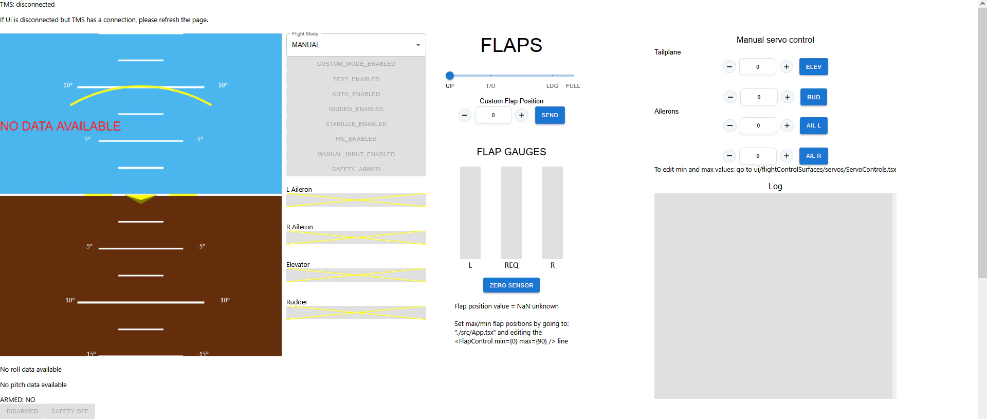
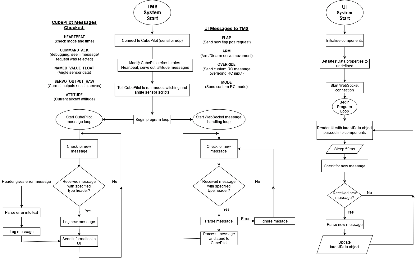
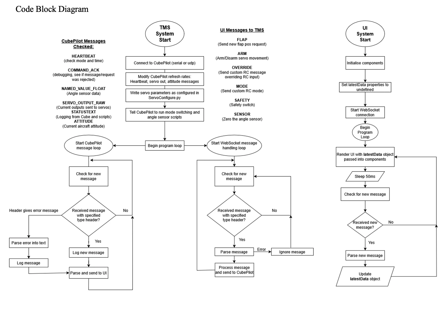
The thirty-seven page group technical report, and the architecture the software sub-team built underneath all of this: a Python and pymavlink telemetry system talking MAVLink over UDP to the CubePilot and WebSockets to a React and TypeScript interface, with Lua scripts onboard for the extra sensor and radio behaviour. I calibrated against it and tested with it rather than writing it.
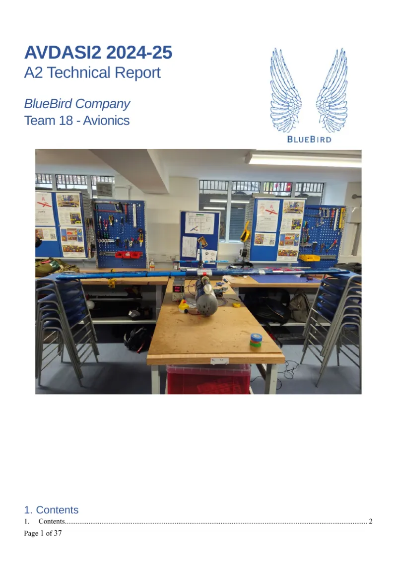 Team 18 avionics technical reportThe group technical report. I wrote the integration and aerodynamics sections and the executive summary.37 pp