BSEP Engine 4
Codename ElsaBristol's first LOx/IPA engine, for Race 2 Space 2026.
Elsa: Bristol's first LOx engine
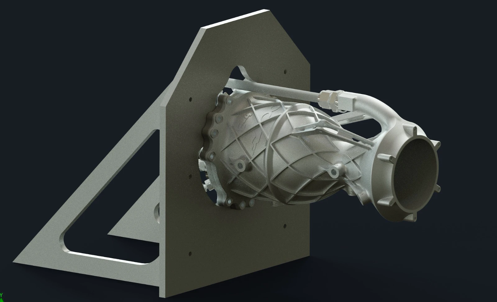
Engine 4 keeps the 5 kN, 20 bar architecture of Engines 1 to 3 and swaps nitrous oxide for liquid oxygen. That one change drove the rest. The chamber goes back to Inconel 718 from CP1 aluminium, because an ox-rich shutdown with LOx has to be survivable. The injector becomes an ox-centred coaxial swirler, which let us delete film cooling. O/F 1.6, IPA fuel, 8 s design burn. Built for Race 2 Space 2026, with Engine 1 declared as the backup: chambers and injectors stay interchangeable across every BSEP engine. The long goal is the 9 km liquid category at EuRoC 2027.
Loading model 0%
Design point
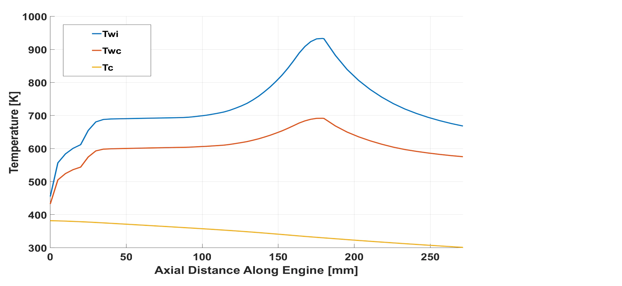
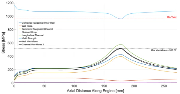
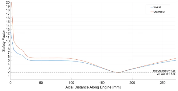
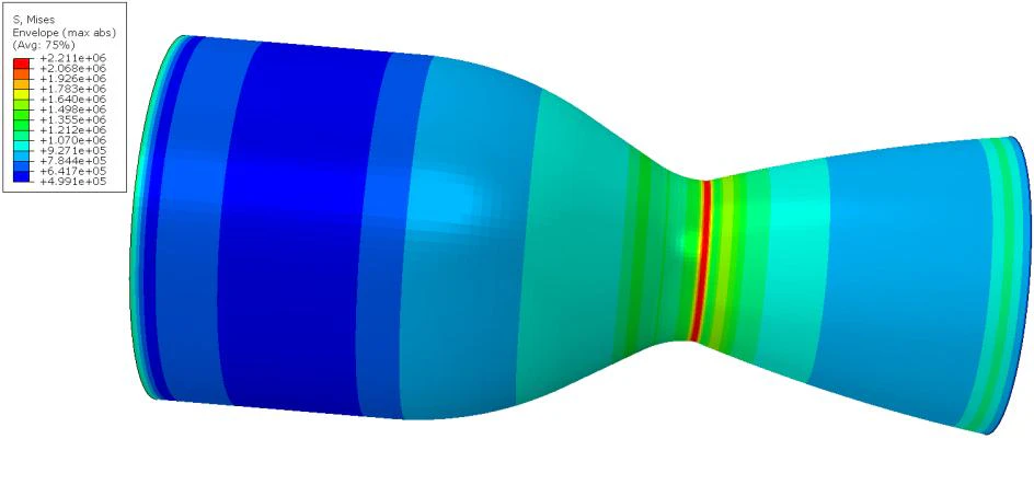
5.0 kN thrust at 20 bar chamber pressure, 30 bar delivery on both sides. O/F 1.6: 0.828 kg/s of IPA against 1.325 kg/s of LOx. The chamber is 281.0 mm long, 117.8 mm across, with a 48.10 mm throat, expansion ratio 3.81 and contraction ratio 6.00. Regen cooling runs through 48 spiral channels at a constant 35 degrees behind a 0.8 mm hot wall, inside an isogrid shell to save mass. Five identical coax swirl elements, sized by the Bazarov method, ox inside and fuel fed to the lower manifold straight from the regen exits. PTFE cryo face seals rated to minus 200 degrees C, a silicone piston seal, no inter-propellant seals. Ignition by the airborne torch igniter. The plots are that design point along the axis: the converged thermal solution from the CDR, the stress and the margin it implies from the PDR. Everything peaks at the throat, and none of it includes the PDMS fuel additive.
The injector
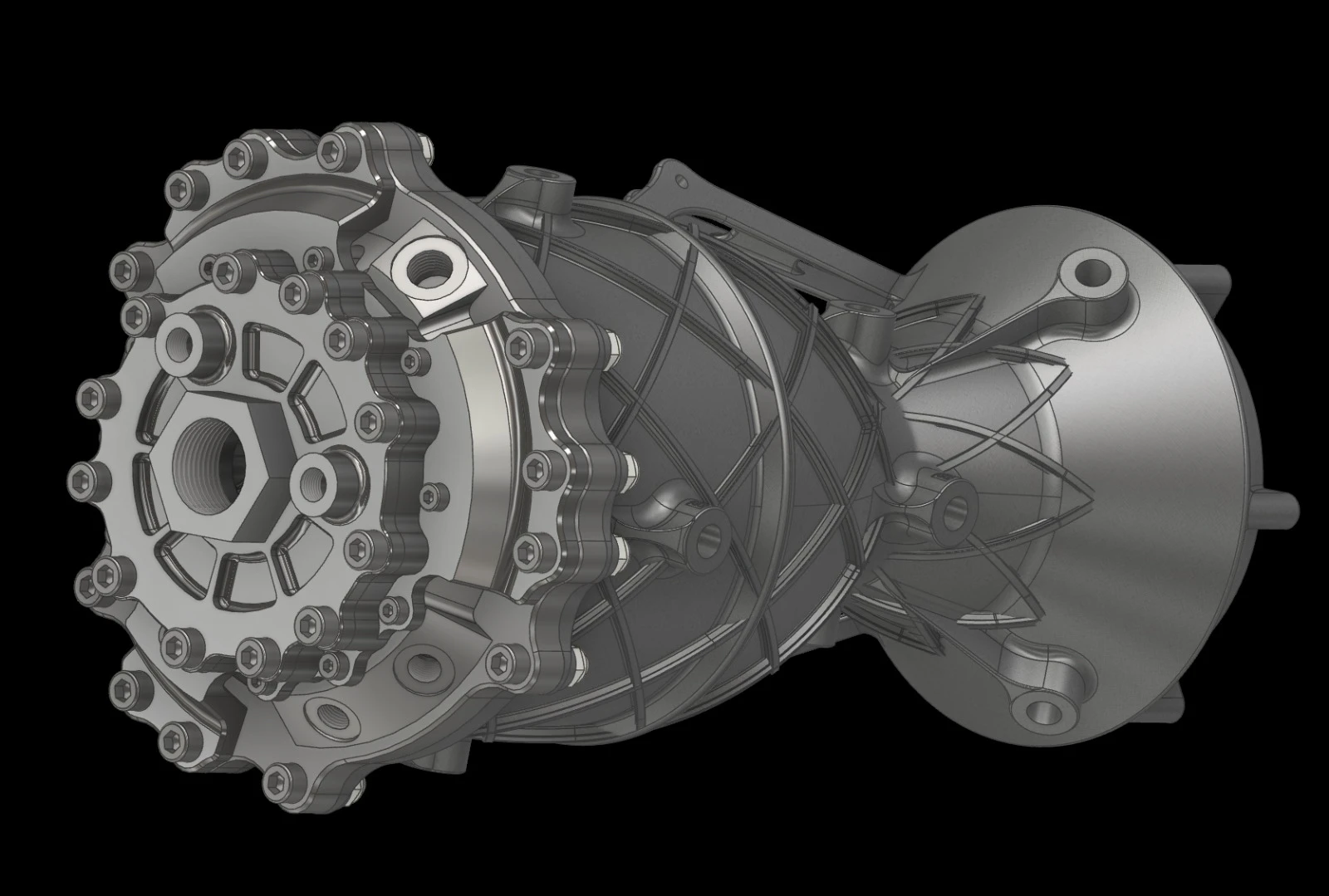
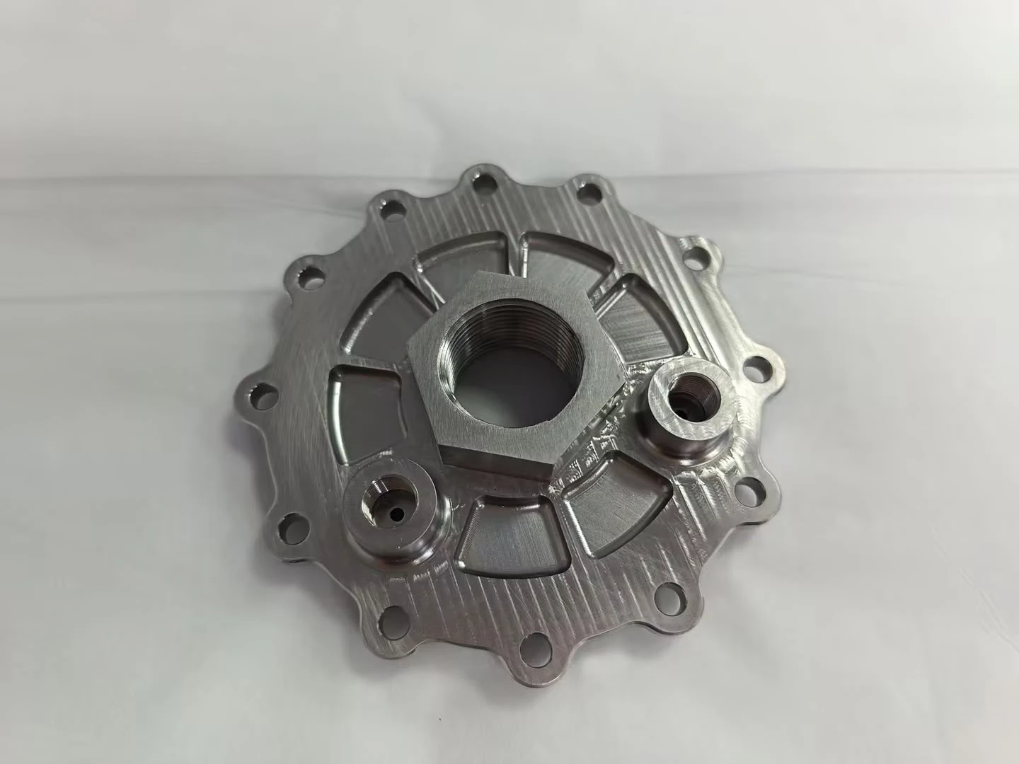
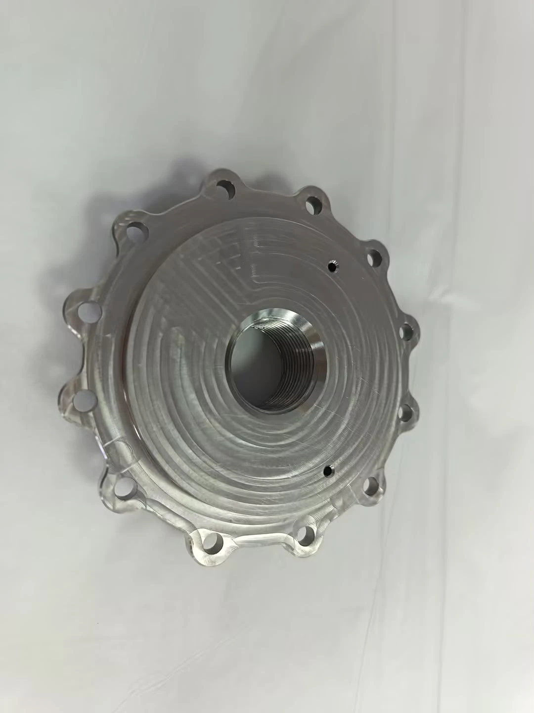
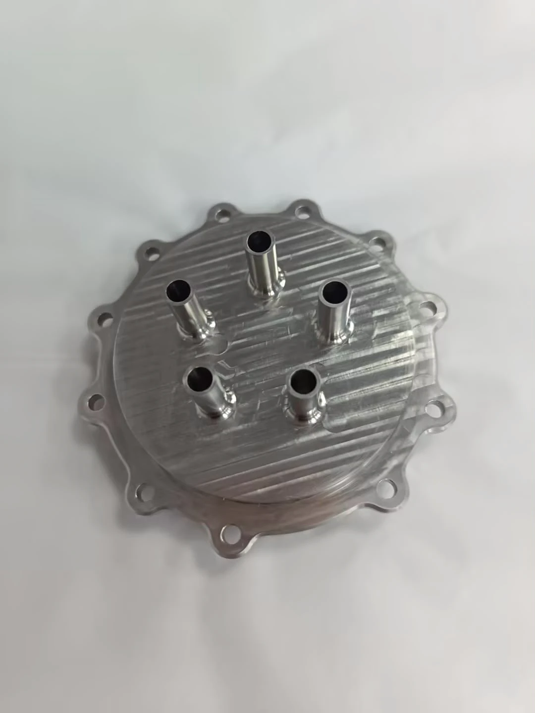
The ox-centred layout is the headline. LOx drops straight through the top plate into the inner swirlers; fuel never has to cross the ox manifold, so the seal count falls. Ox in through a 3/4 inch BSPP port at the centre top, fuel in through 1/2 inch BSPP at the regen inlet. The machined parts arrived in August 2026. Read the strip as the stack, top plate down to the body.

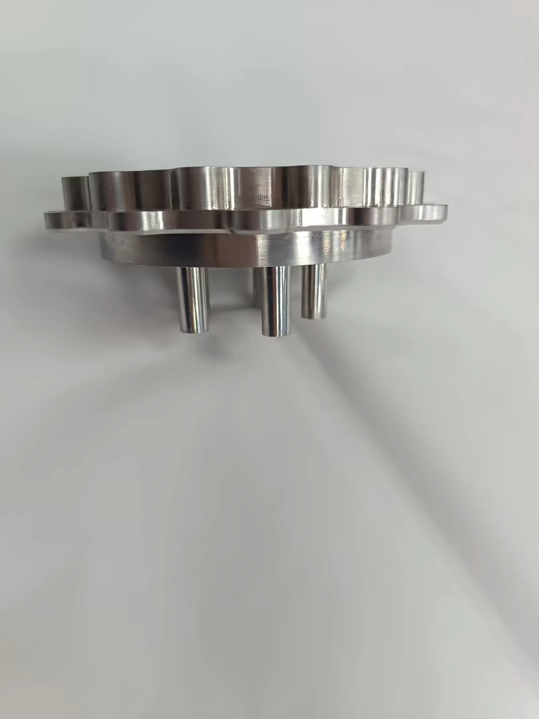
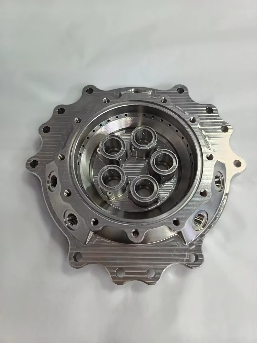
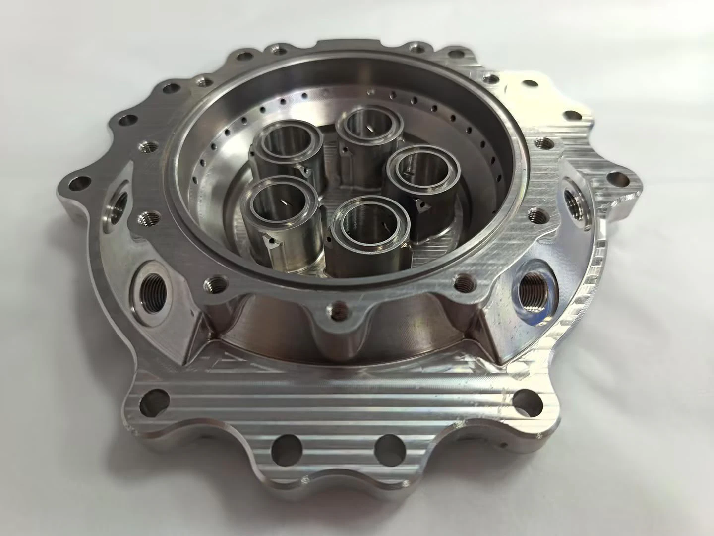
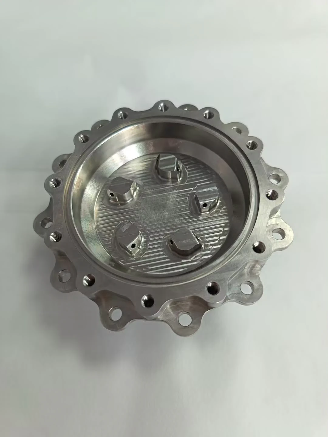
Printed
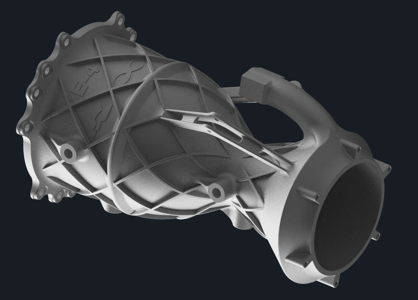
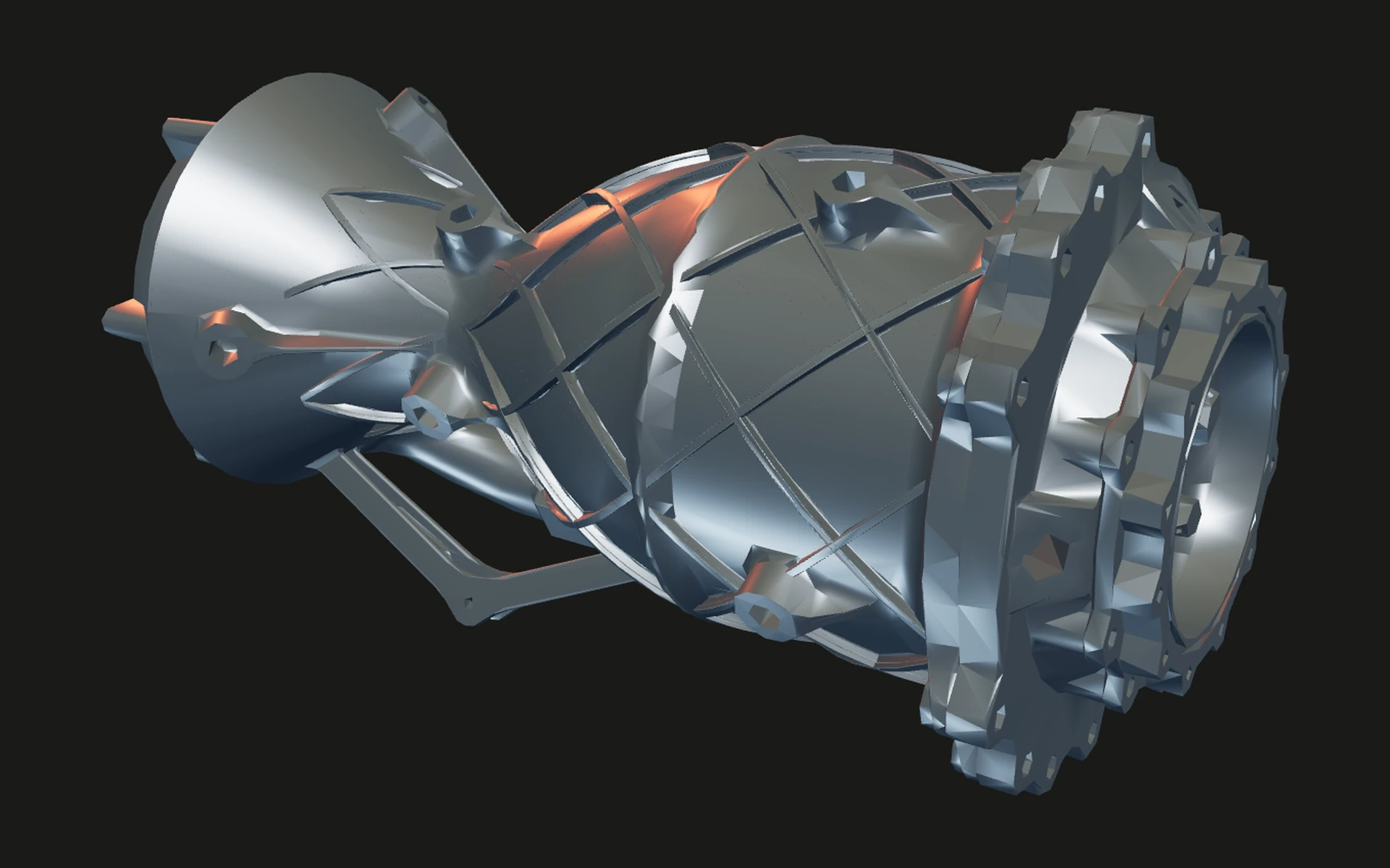
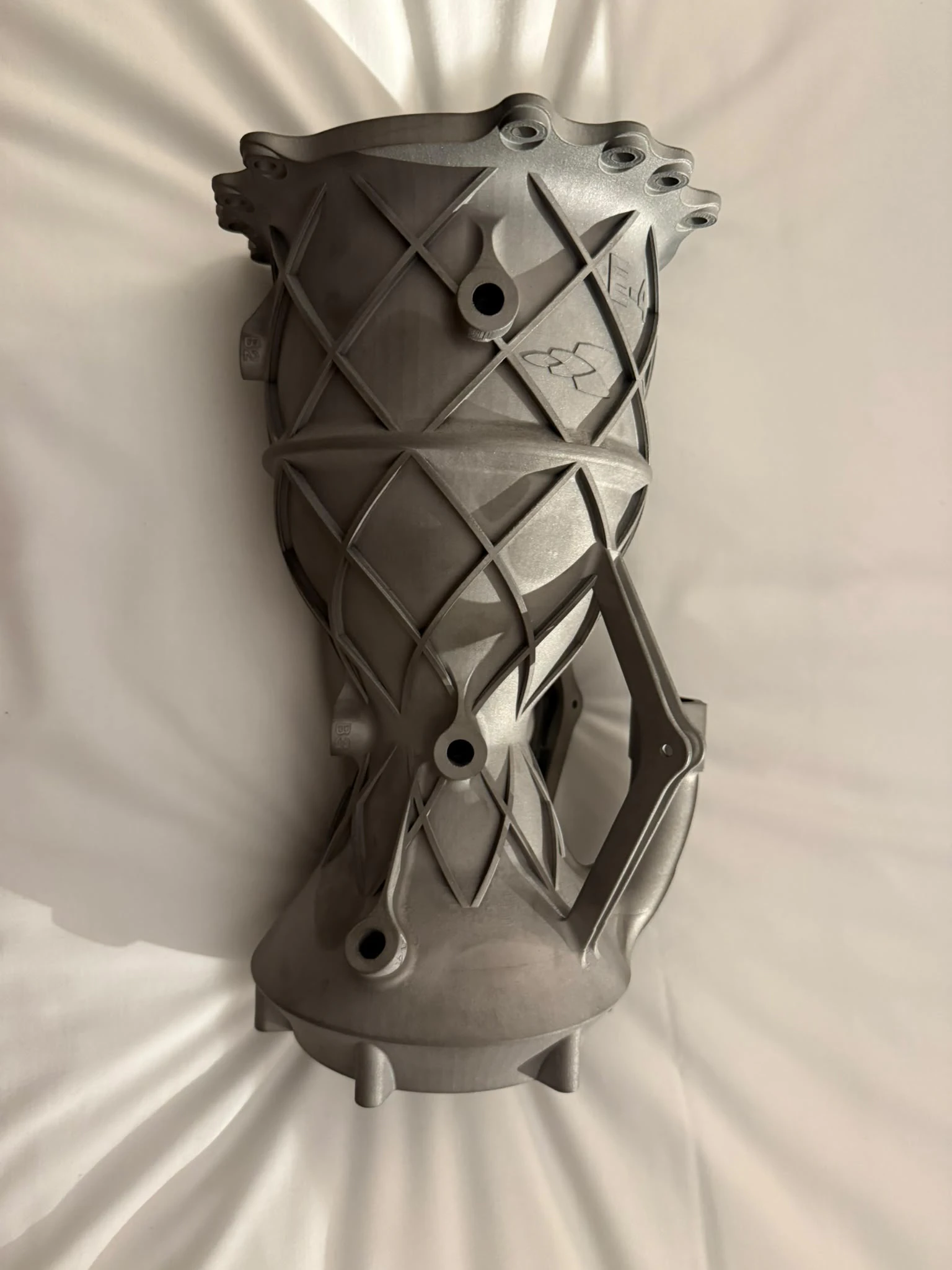
The Inconel 718 chamber came off the LPBF printer in June 2026, brace webs still on. Isogrid lattice, E-4 and the Elsa snowflake embossed on the shell, the same three-quarter framing as the render. Going back to Inconel from CP1 aluminium is what lets a LOx engine survive an off-nominal shutdown, and the chamber stays interchangeable with every other BSEP injector.
Sizing and analysis
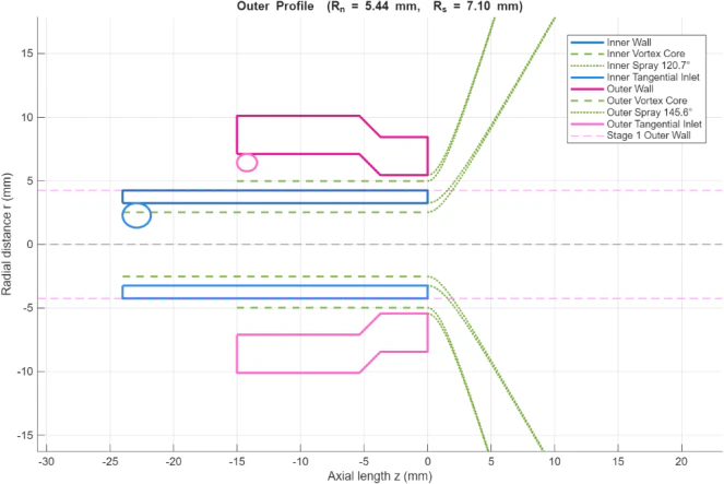
The CDR carries the numbers behind the design point. The five swirl elements are sized by the Bazarov method, iterated until the injector parameters converge; the plot below is one element, inner and outer spray cones on a tip-mixing scheme. Cold-flow testing of tip against external mixing settled the scheme: at 8 to 15 bar of water pressure drop, tip mixing mists less.
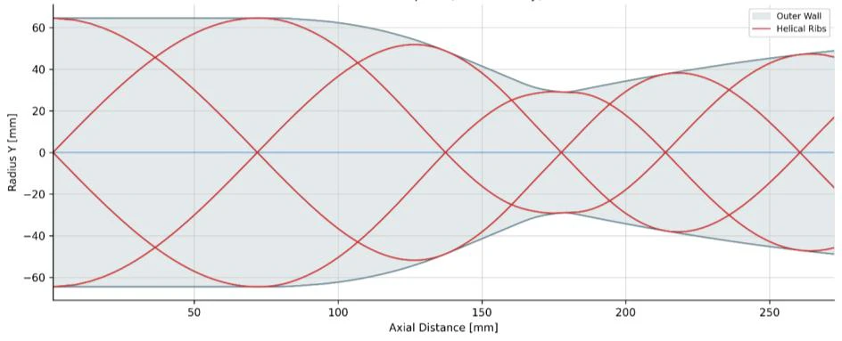
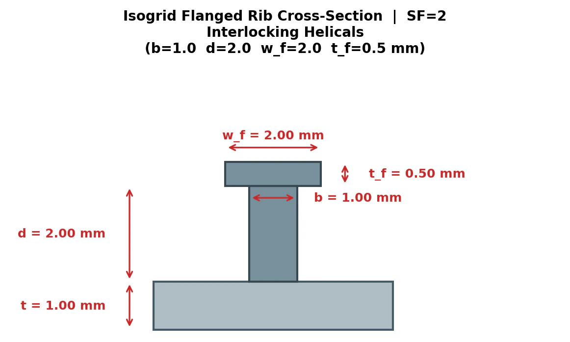
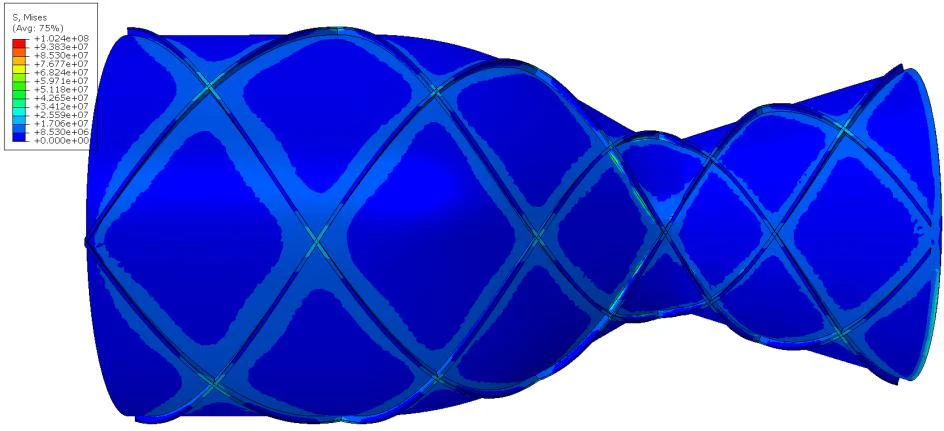
The isogrid is the structural story. A plain 1 mm outer wall under combined thermal and 49 bar pressure loading sits at about 1 GPa of von Mises away from the throat, which against a 1100 MPa yield at 473 K is a safety factor of 1.1 — effectively no margin. The interlocking-helix lattice drops the global average to about 450 MPa and the safety factor to 2.4, close to the smeared NASA-handbook optimiser’s target of 2. These figures are the team’s, from the CDR.
Documents
The Preliminary Design Report from January 2026 and the Critical Design Report from May 2026. The CDR is the canonical document: parameter tables, injector scheme, seals, test plan, sizing calculations, the isogrid appendix and a STAR-CCM exhaust simulation. The test plan is two full-duration burns, then depth of throttle, then increased chamber pressure. Hot-fire status is pending.