Ethan Sheehan
All work ENGINE 03 — 2025-26

BSEP Engine 3

Codename Rapunzel

Spiral-channel regen chamber for EuRoC 2026: designed, printed in CP1 aluminium and CT-scanned end to end, waiting on its first hot fire.
RolePropulsion Lead
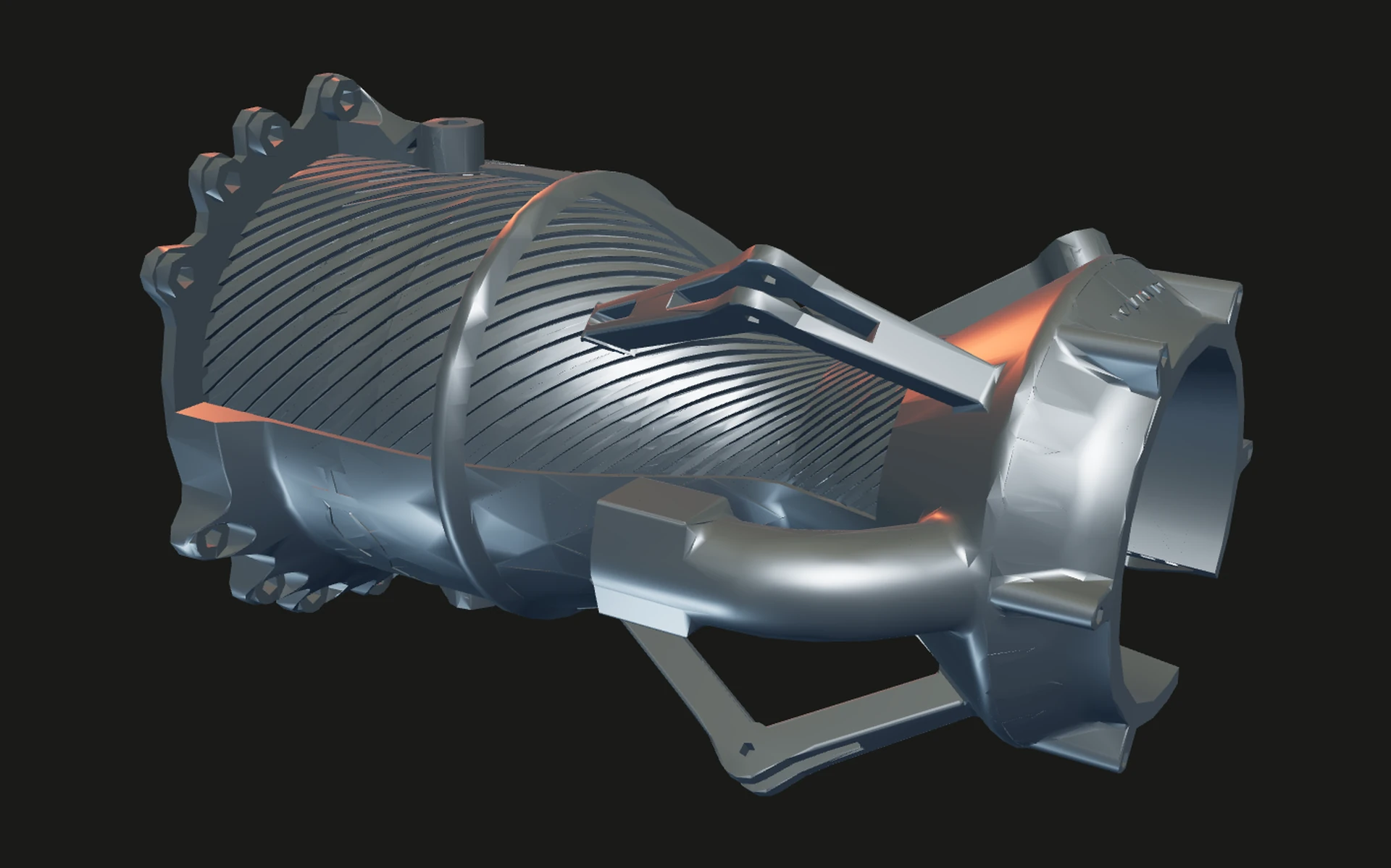
CAD render of the Engine 3 chamber from a three-quarter angle looking into the nozzle, spiral cooling channels wrapping the outer wall and three mounting struts reaching the exit flange
Design thrust
5 kN
Channels
56 spiral
Peak wall temp
-31.6 K at 27°
01

Rapunzel

Engine 3 is the spiral-channel variant of Engine 2, built as the engine of HyPower's DC3 vehicle Tempest for EuRoC 2026. Same cycle and design point: 5 kN, 20 bar, IPA and nitrous oxide at an O/F of 3, a printed Aheadd CP1 aluminium chamber 274 mm long, film cooling at 15 percent and 2 percent PDMS in the fuel. The one deliberate change is that the regenerative cooling channels wrap around the chamber instead of running straight along it. The injector is the fuel-centred coaxial swirl plate that survived the Engine 2 burnthrough, carried over unchanged.
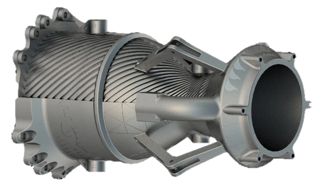
CAD render of the Engine 3 chamber from a three-quarter angle looking into the nozzle, spiral cooling channels wrapping the outer wall and three mounting struts reaching the exit flange
CAD render, three-quarter view into the nozzle.
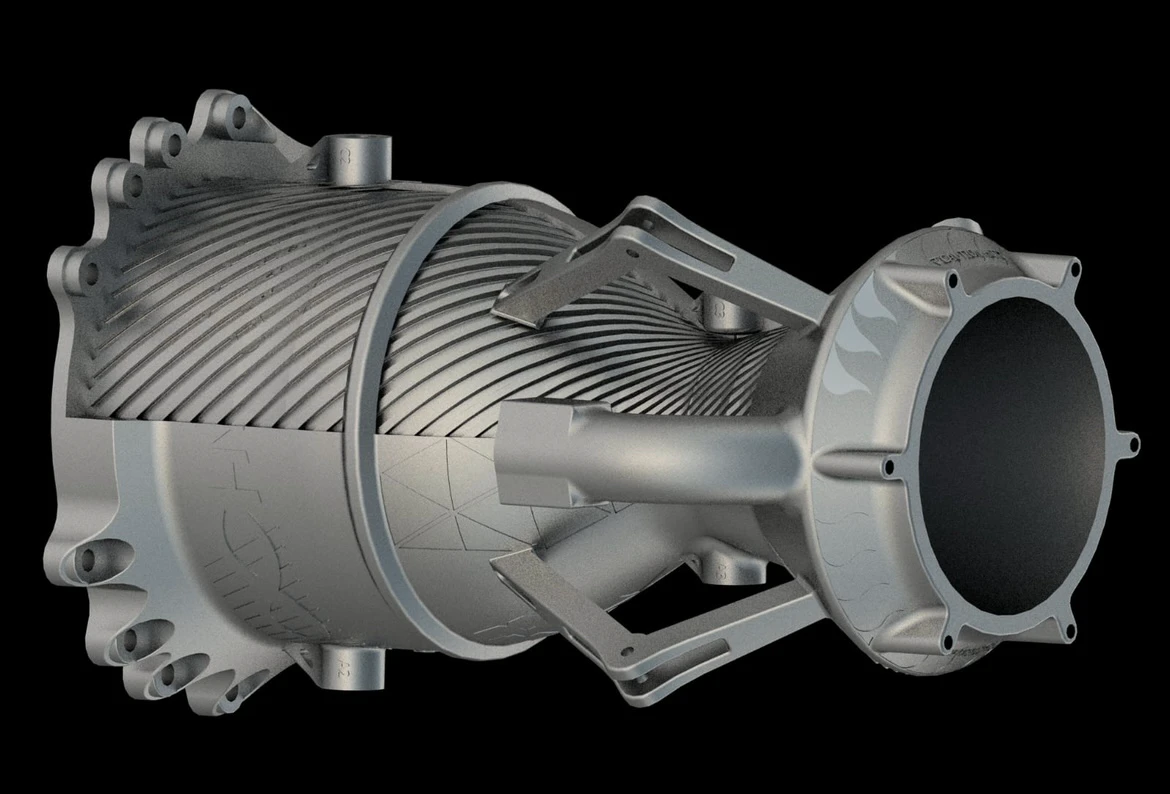
CAD render of the Engine 3 chamber in side profile with the spiral regenerative channels visible along the length and the injector flange on the right
Side profile: spiral regen channels wrapping the chamber, injector end right.
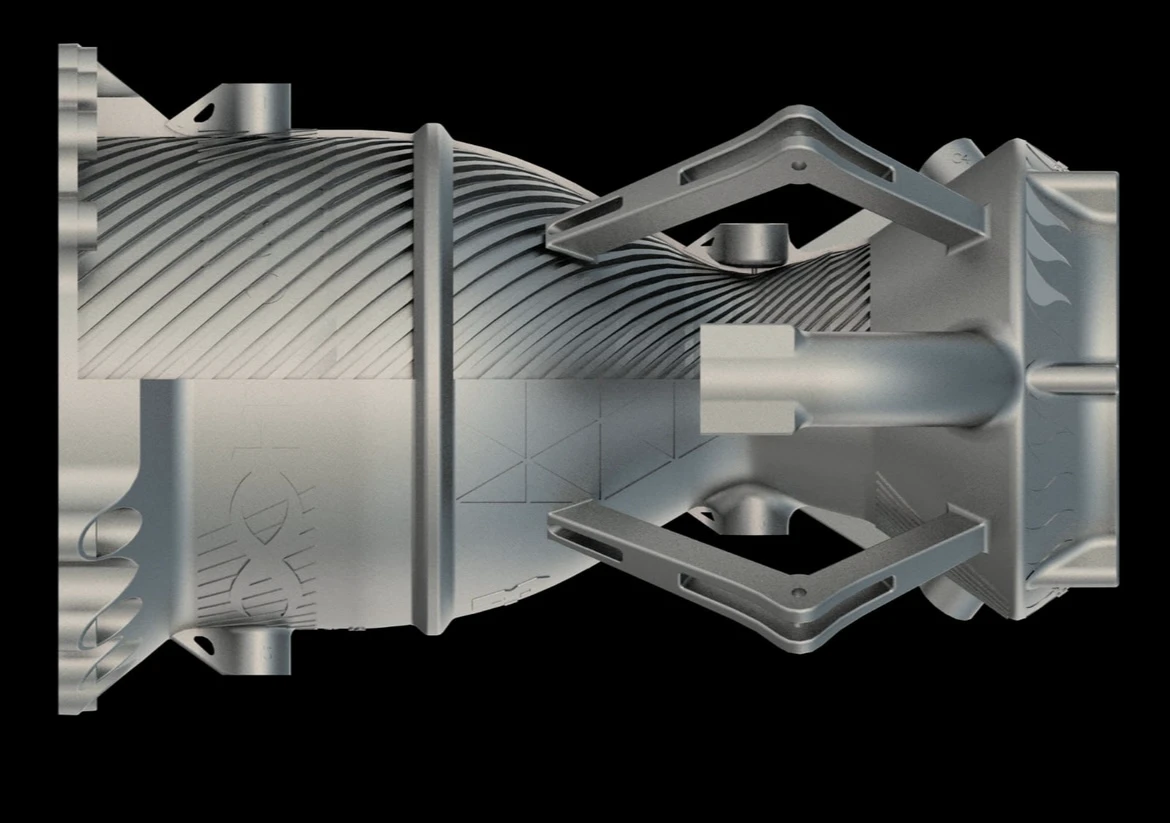
Small deck render of the chamber on a transparent background, spiral channels and mounting struts visible
Render from the propulsion deck.
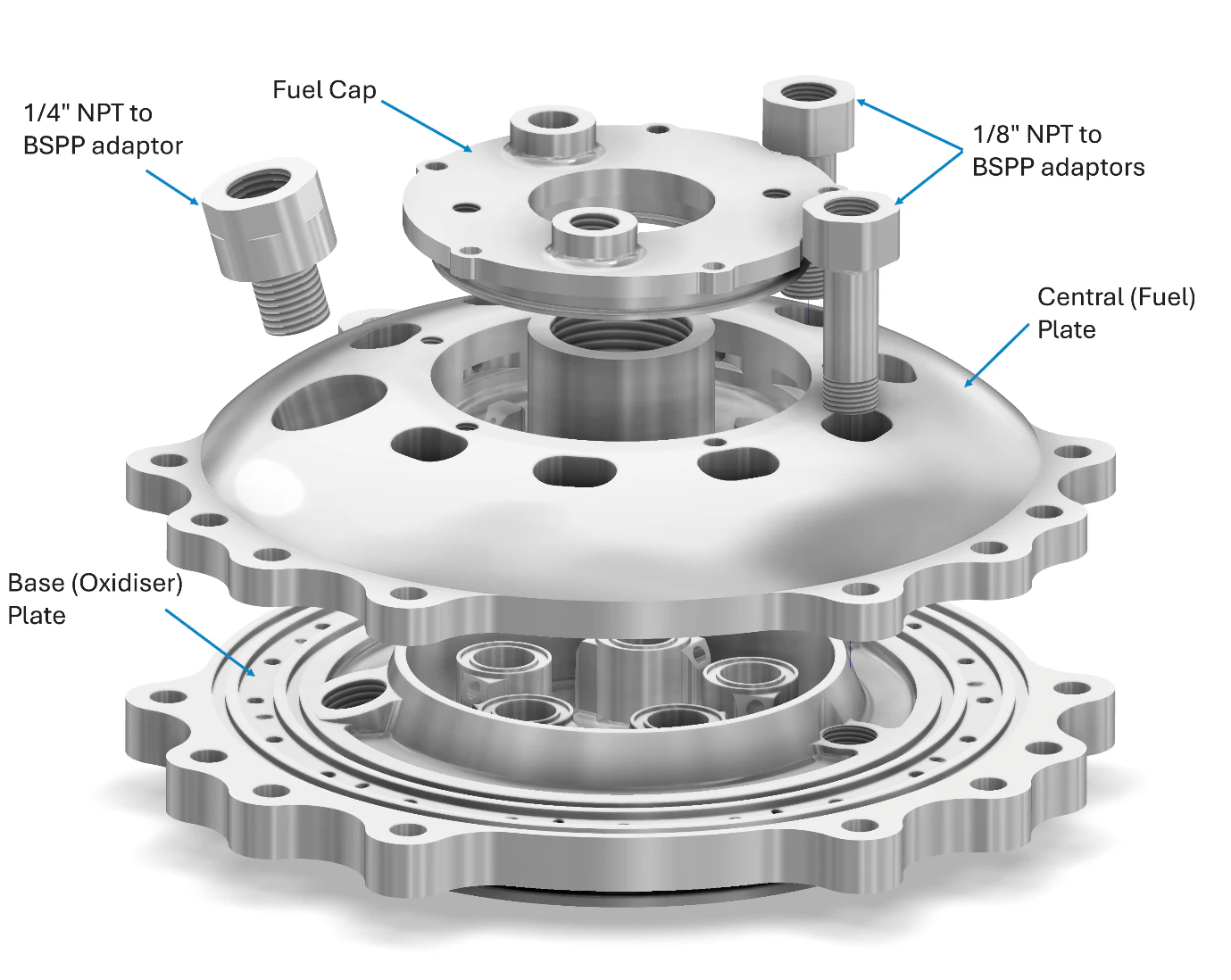
Labelled exploded CAD view of the coaxial-swirl injector: base oxidiser plate, domed central fuel plate, fuel cap and the NPT to BSPP adaptors
Exploded view of the coaxial-swirl injector: base (oxidiser) plate, central (fuel) plate, fuel cap, NPT to BSPP adaptors. Shared design with Engine 2.
02

The spiral-channel trade

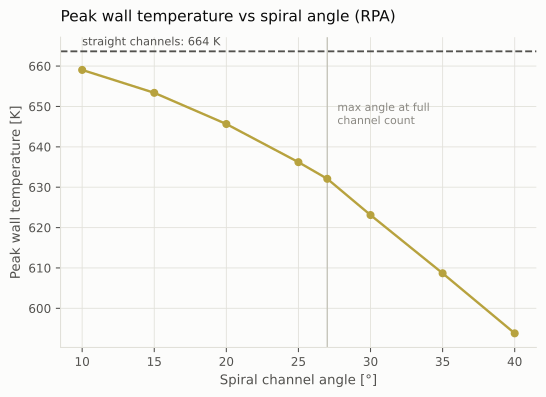
I swept the spiral angle from 10 to 40 degrees in RPA against the straight-channel baseline, tracking hot-side wall temperature along the chamber with no PDMS in the fuel. The straight channels peak at 663.7 K, 176.8 mm down the chamber in the throat region. A steeper spiral lengthens the coolant path and pulls that peak down, but past a point the channels no longer fit and the count has to drop. 27 degrees is the steepest angle that keeps all 56 channels, and it takes the peak to 632.1 K, a 31.6 K cut. 40 degrees reaches 593.7 K, but only with fewer channels.
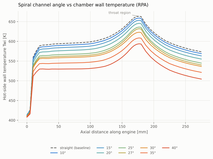
Hot-side wall temperature against axial station for the straight-channel baseline and spiral angles from 10 to 40 degrees, every curve peaking near the throat
Twi vs axial station: straight baseline (dashed) and 10 to 40 degree spirals. RPA, no PDMS.
Peak wall temperature falling as spiral angle increases, with 27 degrees marked as the steepest angle that keeps all 56 channels
Peak Twi vs spiral angle. 27 degrees marked as the maximum angle at full channel count.
03

Powder bed

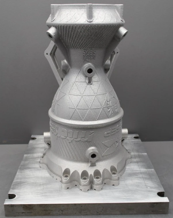
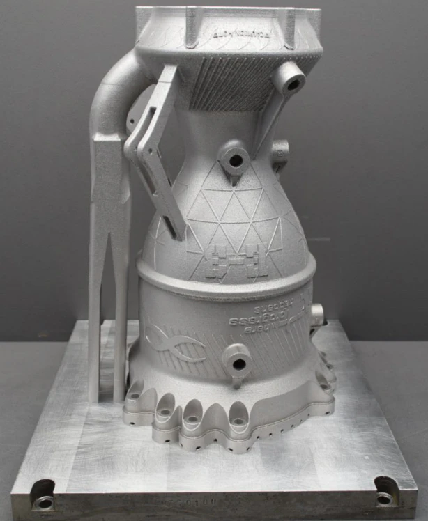
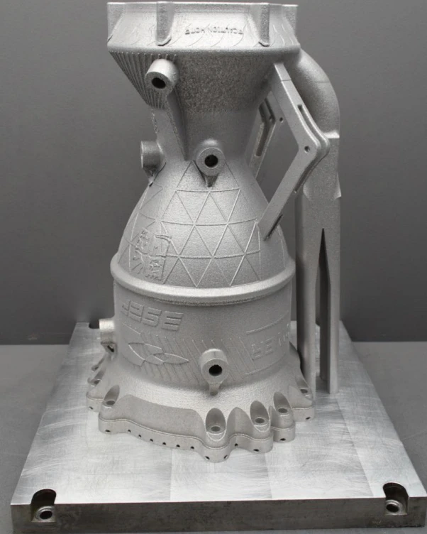
The chamber was printed in Aheadd CP1 aluminium by laser powder bed fusion. The build camera caught the flange cross-section fusing into a fresh powder layer, and earlier the chamber wall ring with a support section beside it. Off the machine the part sits inverted on its build plate with a printed support strut behind it, the nozzle section lattice-textured, the flange scallops still rough, and BSEP, HyPower and MTC marks embossed in the skin.
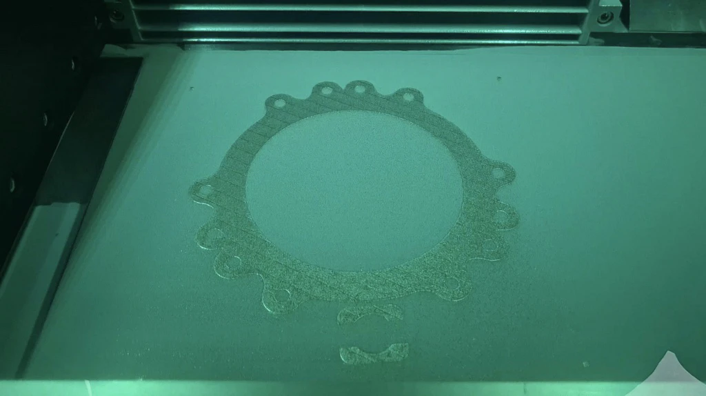
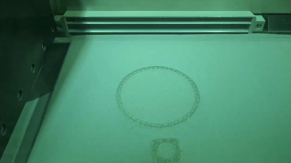
Build-camera frame of the powder bed mid-print with the fused cross-section of the chamber flange standing out against fresh grey powder
Powder bed mid-build: the flange cross-section fused into the fresh layer.
Build-camera frame from an earlier layer showing the ring of the chamber wall and a support cross-section in the powder
An earlier layer: chamber wall ring and a support cross-section.
As-printed aluminium chamber standing inverted on its build plate with a printed support strut behind and BSEP and MTC marks embossed in the skin
As printed, inverted on the build plate. BSEP and MTC embossing.
Three-quarter view of the as-printed chamber showing the lattice-textured nozzle section and the scalloped flange
Three-quarter view: lattice-textured nozzle section and flange scallops.
Reverse angle of the as-printed chamber on its build plate with the support strut on the right
Reverse angle, support strut right.
04

Through the metal

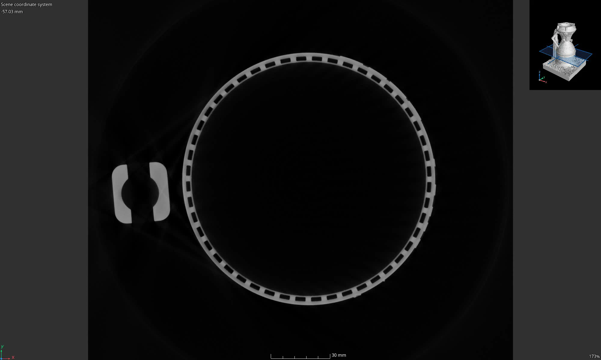
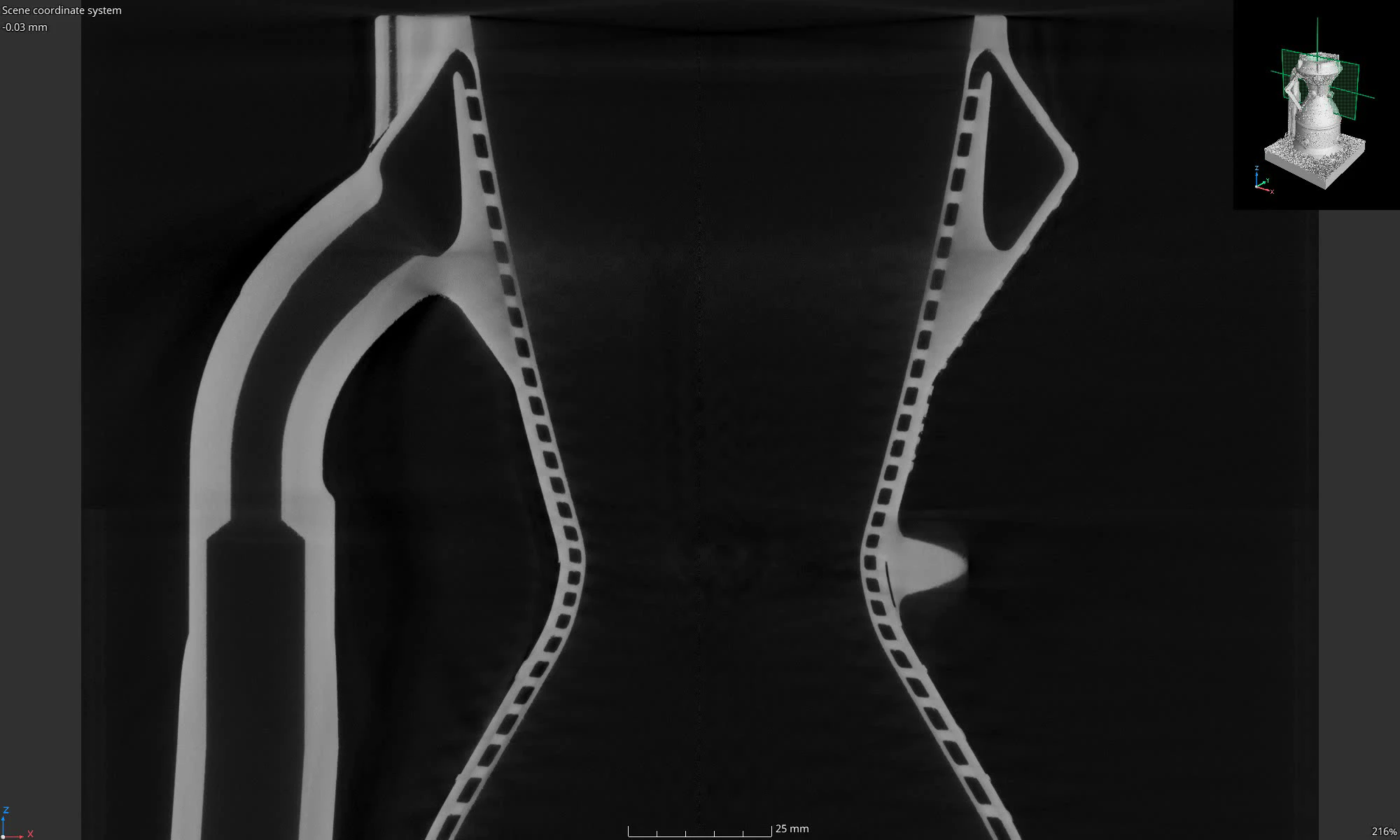
The printed chamber went to X-ray CT before it ever saw propellant — the whole point, after Engine 2 was lost to swarf left in its cooling channels. The vertical sweep walks a slice plane through the full chamber: the hourglass profile with the spiral channels reading as a dashed line of voids down both walls. Then the same sweep framed on the throat, a custom-path section that follows one channel around the chamber, and the horizontal sweep, where mid-chamber slices show the complete ring of channel voids around the liner.
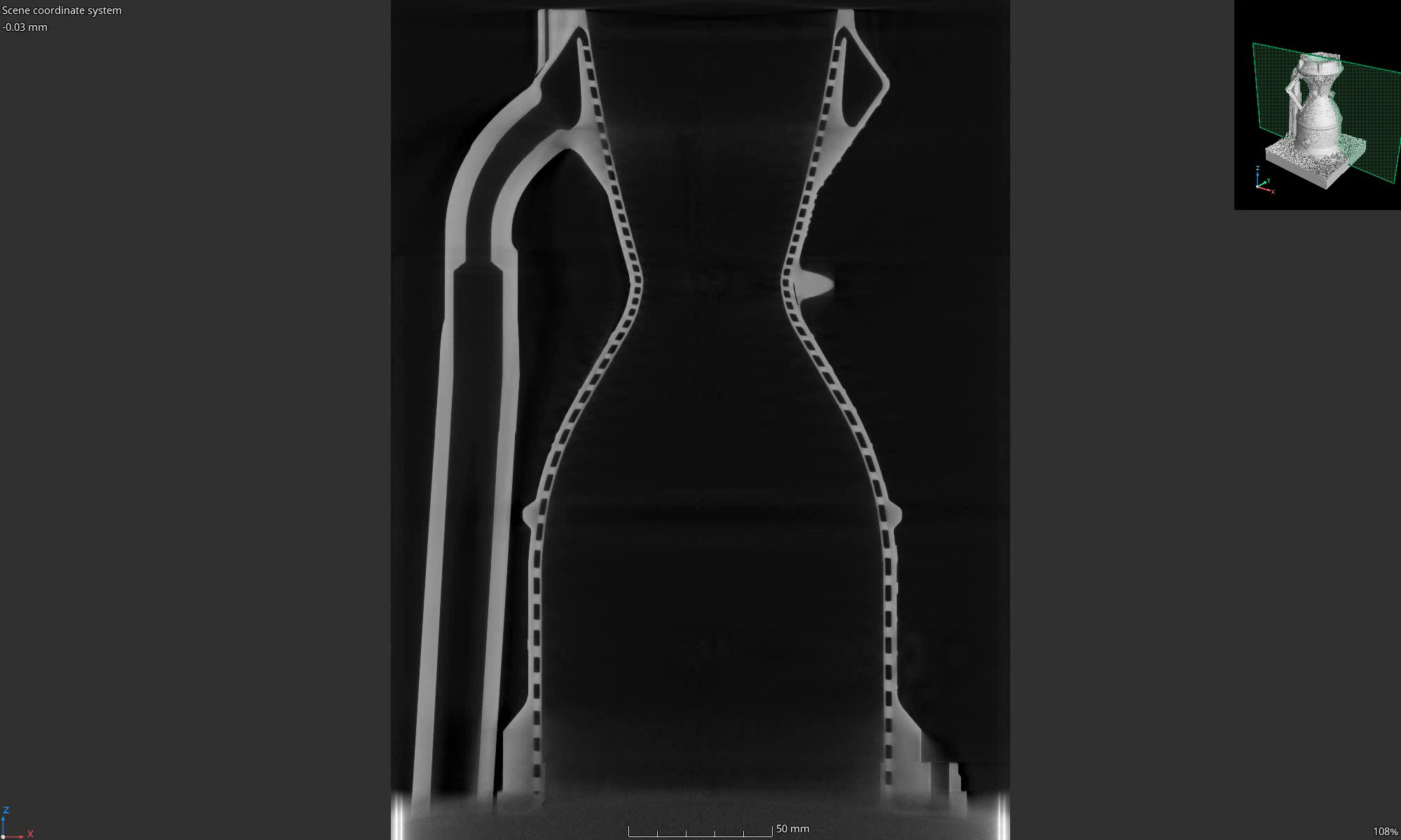
Vertical (XZ) CT sweep through the full chamber: channels dashed down both walls.
Vertical (XZ) CT slice sweep framed on the throat region.
Custom-path CT section following one spiral channel around the chamber. From the MTC analysis.
Horizontal (XY) CT slice sweep through the mid-chamber. The full channel ring around the liner.
Single X-ray CT vertical section at the chamber centreline showing the hourglass profile with channel voids dashed along both walls
Full XZ section at the chamber centreline.
Single X-ray CT vertical section of the throat region with channel voids dashed along the converging walls
Throat-region XZ section.
Single X-ray CT horizontal section mid-chamber showing the complete ring of channel voids around the liner
XY section mid-chamber: the full ring of channel voids.
05

Not yet fired

Engine 3 is manufactured and inspected but has not been hot-fired. It is waiting on the EuRoC 2026 campaign. When it fires, this page gets a test section and plots to the same convention as Engines 1 and 2.